
Wayne's pool cue fixit place

- WELCOME -
THIS SITE IS STRICTLY INFORMATIONAL
THIS SITE IS STRICTLY INFORMATIONAL
TIPS ON TIPS - ALMOST ALL I KNOW ABOUT
CUE TIP AND FERRULE REPAIR
PLUS
ADAPTATION OF A MINI LATHE FOR CUE REPAIR USE
BEWARE - I AM PRONE TO DETAIL BECAUSE:
CUE TIP AND FERRULE REPAIR
PLUS
ADAPTATION OF A MINI LATHE FOR CUE REPAIR USE
BEWARE - I AM PRONE TO DETAIL BECAUSE:

I HAVE WORKED WITH TOOLS ALL MY LIFE
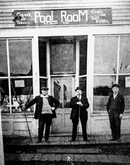
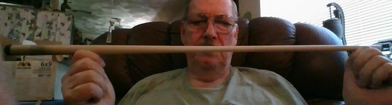
NOW THAT I'M I RETIRED I SHOOT POOL
NOW THAT I'M I RETIRED I SHOOT POOL

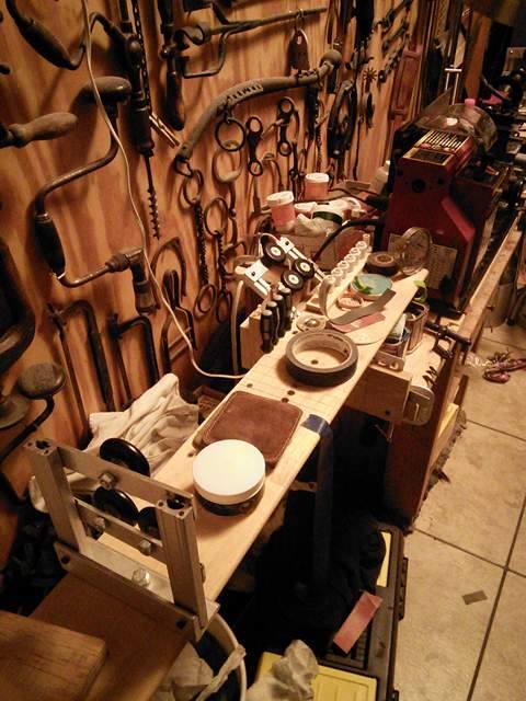
THIS IS MY MANCAVE. THE POOL TABLE IS MY RESTORATION OF A TERRIBLY BEAT UP ANTIQUE BRUNSWICK "DEFIANCE" MADE FROM SOLID GUM WOOD. THE DECAL UNDER THE RAIL SHOWS A FINAL PATENT DATE OF 1923. THAT'S BENNIE, MY GUEST.
MY INVENTION
MY NAME IS WAYNE HESTER......
MY UNDYING APPRECIATION GOES TO MY WONDERFUL WIFE AND HELPMATE, DEBBIE, WHO MADE MANY OF THE PHOTOS SEEN HERE.

AT THE SENIOR CENTER PLAYING POOL SIX MONTHS AFTER SECOND BACK SURGERY. YES I LOVE POOL
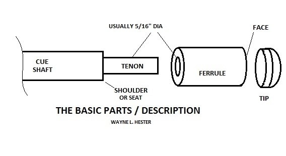
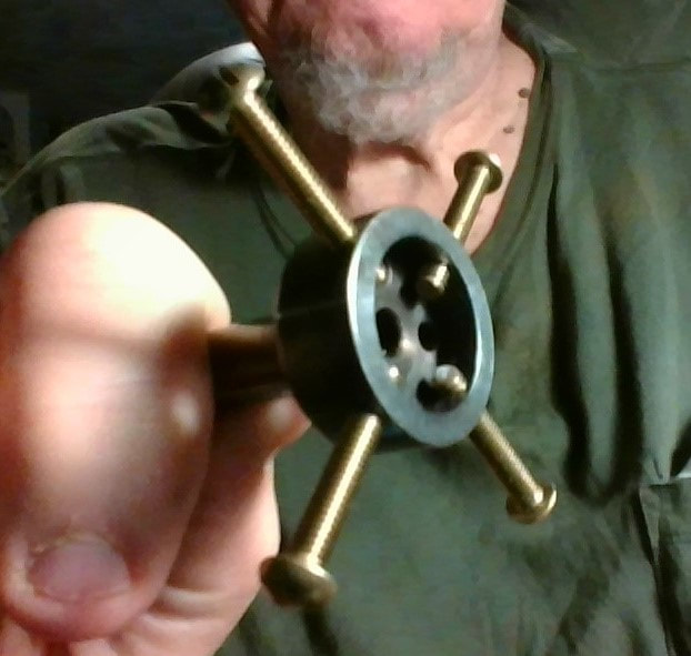
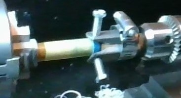
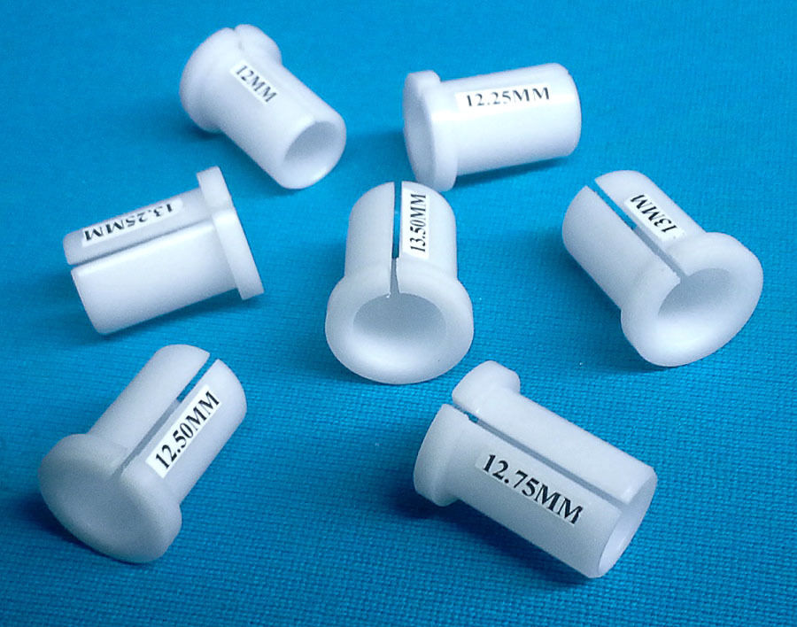
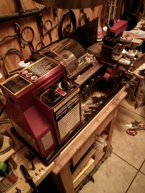
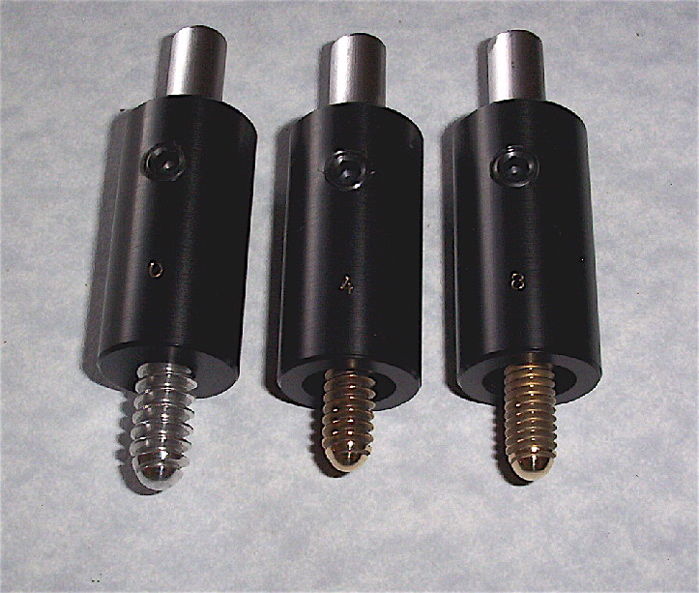
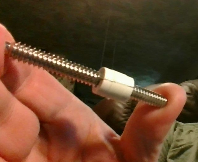
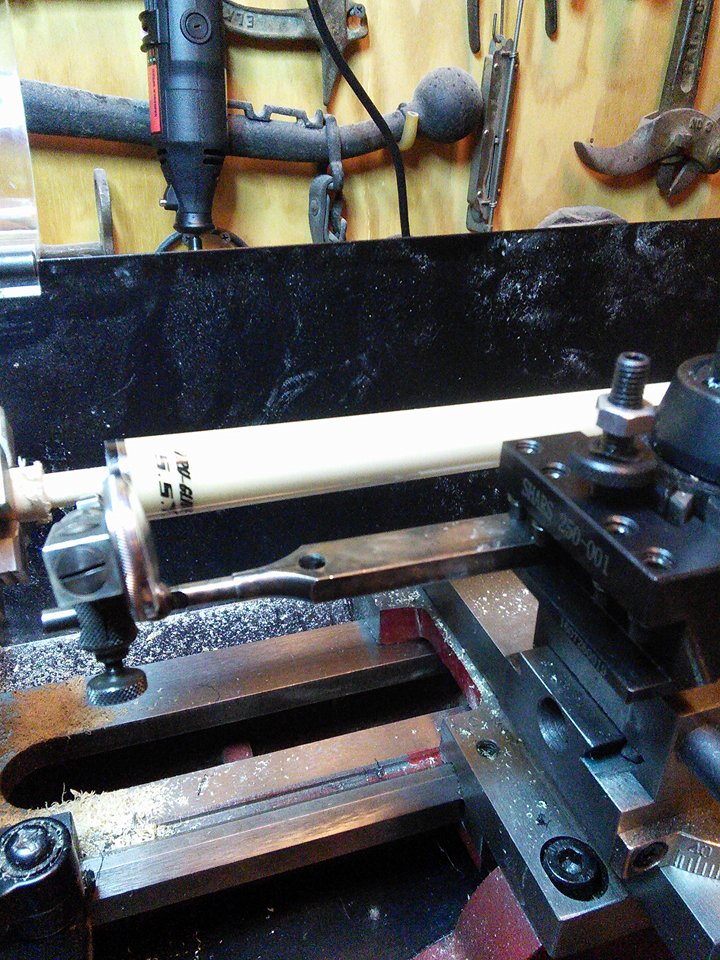
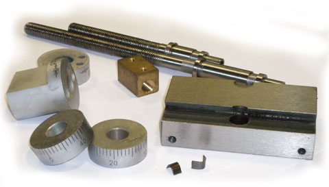
IN THIS WEBSITE I'LL BE DISCUSSING POOL CUE REPAIRS RELATING TO THE PARTS (ABOVE) USING THE MACHINE (BELOW)
WHICH I ADAPTED WITH OUTRIGGERS TO HOLD CUES.
WHICH I ADAPTED WITH OUTRIGGERS TO HOLD CUES.
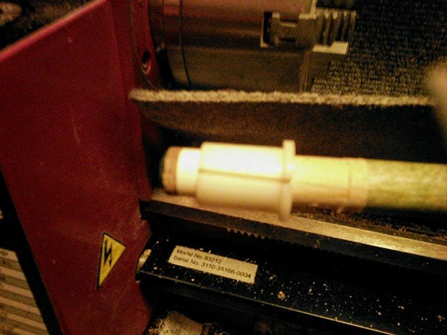
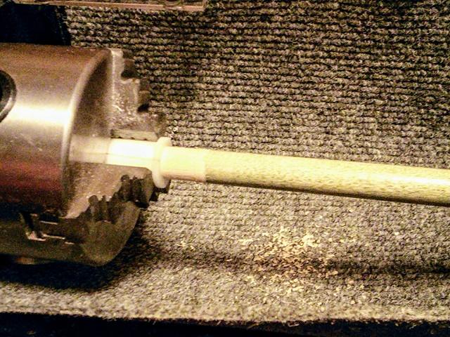
HOW IT ALL BEGAN. I started repairing pool cues by voluntarily re-tipping the house cues for my local Senior Center the old fashioned way using a hand cranked face sander and tip clamps. These guys at the Senior Center are old but they break the rack hard as you can see in the photo below.
I repaired this cue by cutting a new tenon with a mini lathe and installing a new ferrule and tip. It is 2" shorter than before but nobody at the Senior Center cares, they just want to break a rack with it and may end up breaking the stick again. Soon I began to install phenolic break tips on some of these house cues and I asked the heavy explosive breakers to use them. I will describe my work with cues in this article.
PHENOLIC BREAK FERRULES

IDEA FOR A LATHE. After replacing tips by hand a few months for the Senior Center, people were asking me to tip their personal cues. I knew there must be a better way so I decided to get a lathe. I didn't want to spend $2100.00 for a good cue tip lathe and the cheaper ones weren't so good. I am a disabled arthritic and wood lathes with tool rests would not work with my shaky hands, plus not the best for cue repair. I decided I needed a metal cutting, machine lathe and I found the harbor freight model mini-lathe attractive. I purchased one and adapted it for house cues and personal cue shafts to replace tips and/or ferrules as well as a variety of other tasks. I am not a retired machinist, I am a retired electrician so I researched and used trial and error methods working with dowels and then cues to become what I consider proficient in turning out a better than new shaft end cue repair job. These are my experiences with repairing cues, yours may be easier and may even be better but the info below is from my experience of 5 years with this lathe and I am satisfied as are my friends who get a top rate repair job at less than half or one-third the price of a professional. My objective is only to help my friends with their cues and I am not pursuing a profit. I worked at jobs for 50 years and I don't want to start again. A hobby can become a job, then the fun is gone. My equipment is relatively inexpensive. The $5000.00 + lathes and the additional thousands of dollars worth of accessories are great but I will leave these to the career cue builder.

DECIDING ON WHETHER TO BUY EXPENSIVE CUE BUILDING EQUIPMENT OR JUST A HOBBY LATHE
DEPENDS ON HOW FAR YOU WANT TO GO. DO I SEEK A CAREER, DO I SEEK A HOBBY OR SOMETHING IN BETWEEN? AND HOW MUCH MONEY DO I WANT TO SPEND? DO I WANT TO SHOOT POOL OR WORK? LOL
DEPENDS ON HOW FAR YOU WANT TO GO. DO I SEEK A CAREER, DO I SEEK A HOBBY OR SOMETHING IN BETWEEN? AND HOW MUCH MONEY DO I WANT TO SPEND? DO I WANT TO SHOOT POOL OR WORK? LOL

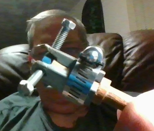
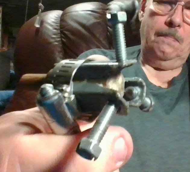
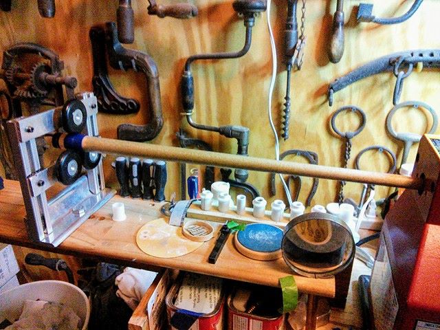
ULTIMATE LATHE USE TIP HOLDER - MY INVENTION. I have made two different styles of cue tip centering tools for use on my hobby lathe. The core of these tools are cut from a 3/4" oak dowel. I use them by chucking them to the tailstock drill chuck. The body of this tool is made of wood, and hand tight is all that's needed to chuck the tool. The first ones I made needed a tool for each size tip and were not as reliable. The best one, which I will discuss here, is one size fits all, made with three old sink clamps attached to the dowel with a radiator clamp and once clamped a bead of glue is applied on each side of each sink clamp to help retain the position of the metal to the wood. Before assembling the clamps to the dowel I removed the screws and ground the ends of the clamps which made for better access and viewing. I also ground the ends of the screws smooth where they will make contact with the side of the tips. Three sink clamps are used with their screws to position the tip to the exact center. Other metal material, such as small aluminum U stock, drilled and tapped, may be used in place of the sink clamps to make this holder. I just happened to have these sink clamps because I replaced a bathroom sink years ago and I NEVER throw away any screws or useful looking hardware. The enterprising machinist could even make the whole thing from solid aluminum or steel stock and add three knurled head screws for a very fancy tip placement tool.

MY EARLIER TIP HOLDERS, ONE FOR 13MM AND ANOTHER FOR 14MM TIPS. I STARTED USING THESE WITH THE PRONGS STRAIGHT AND BENT THEM LATER. BEFORE THE RADIATOR CLAMPS WERE USED THEY HAD RUBBER BANDS HOLDING THE THREE PRONGS IN PLACE. I GLUED A LOT OF TIPS ON WITH THESE BEFORE I MADE A BETTER ONE (BELOW)
|
|
WAYNE'S ULTIMATE "LATHE USE" TIP HOLDER
-TIP PLACEMENT TOOL-
MADE FROM A WOODEN DOWEL, THREE OLD SINK CLAMPS
AND AN AUTOMOTIVE TYPE TUBING CLAMP.
-TIP PLACEMENT TOOL-
MADE FROM A WOODEN DOWEL, THREE OLD SINK CLAMPS
AND AN AUTOMOTIVE TYPE TUBING CLAMP.
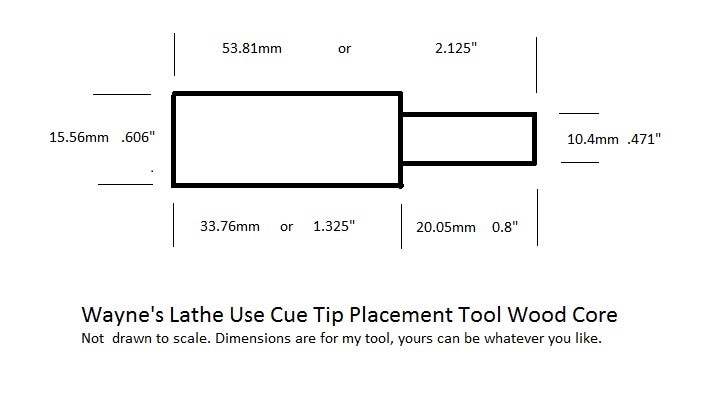
Here are the measurements to which the dowel was cut for making the tip holder body. I didn't really measure anything but just made it from feel. The measurements above are what turned up. The wood is oak.
USING THE TIP HOLDER PLACEMENT TOOL IN THE LATHE. The tip holder unit is mounted to the tailstock drill chuck with tip already set up in the holder. Then the holder is run up to the ferrule using the tailstock wheel. I use a toothpick to check three sides by feel to check positioning of the tip in relation to the ferrule that the drop from tip to ferrule on all three sides are even. Someone with better eyesight may not need the toothpick check. Adjustment to center the tip is made by backing the tip from the ferrule just enough to make a tiny gap then adjusting the three screws as needed to center the tip to the ferrule, then rechecking alignment after re-advancing the tip against the ferrule. The three screws should not be tightened so tight as to prevent the tip from flattening against the face of the ferrule. Next I back the tip off, apply glue and bring it forward again to contact the tip with slight pressure to the ferrule, then, leaving the tailstock holding the tip I back off the three screws and I run the edge of a paper towel under the screws around the ferrule and tip to clean excess glue. After the prescribed glue setting time the tailstock can then be backed off and the tip tool can be removed from the tailstock. Using a 14mm new tip on a 13mm shaft and glueing it with this tool then trimming the overlapping tip flush to the ferrule with the lathe bit makes for a perfect job. Even gluing a 13mm tip to a 13mm ferrule can be accomplished but why do it the hard way? I use the 13mm tips for 12.5 mm ferrules or smaller and sometimes on 12.75mm ferrules.
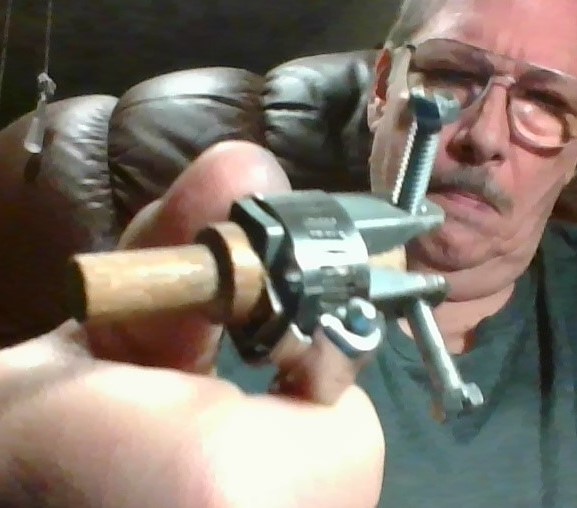
HOLDER WITH AN ELK MASTER (SOFT) TIP READY TO CHUCK ONTO TAILSTOCK
NOTE THAT THE BOTTOM OF THE TIP IS SANDED TO ACCEPT GLUE
NOTE THAT THE BOTTOM OF THE TIP IS SANDED TO ACCEPT GLUE
|
|
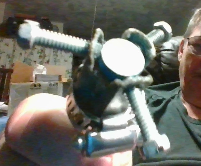
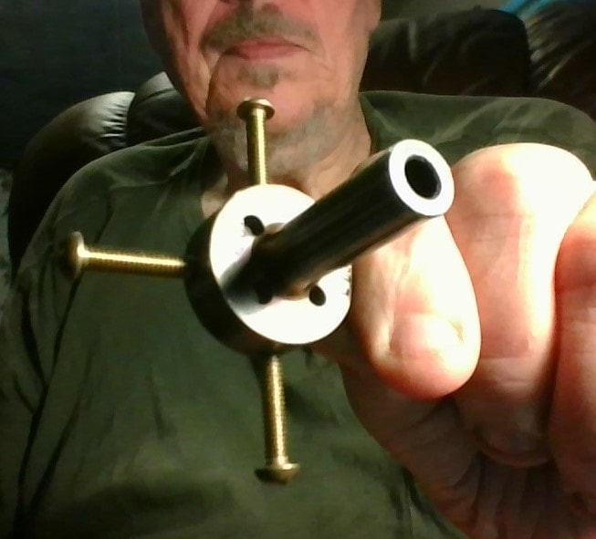
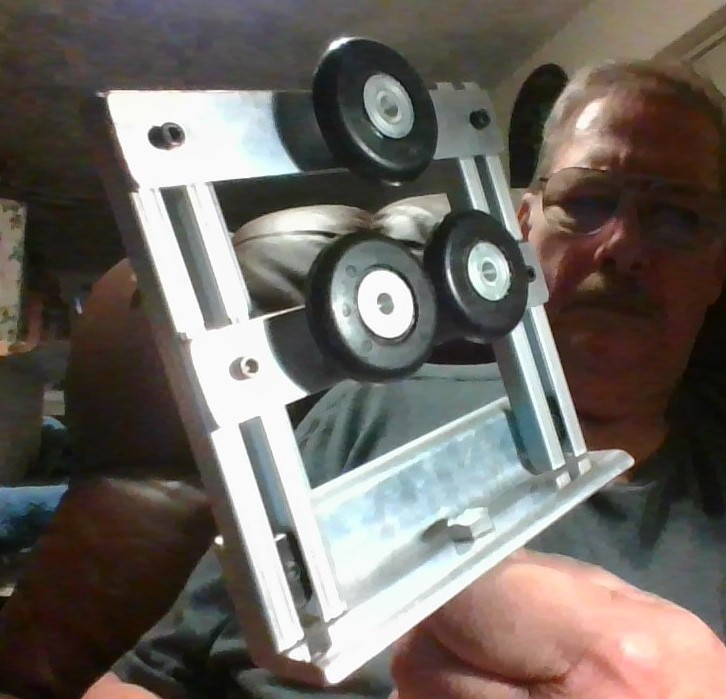
Eventually I ended up with this device which uses four screws and is easier to center the tip.
I found this on ebay which is an unknown device but may be some kind of lathe spider tool .
I found this on ebay which is an unknown device but may be some kind of lathe spider tool .
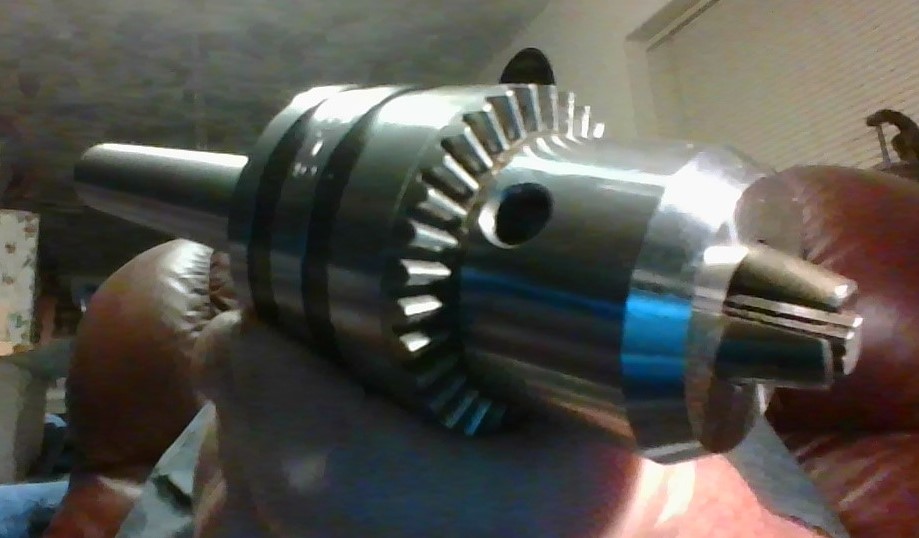
A CLOSEUP OF THE DRILL BIT CHUCK FOR USE IN THE TAILSTOCK. THE SHAFT, OR ARBOR, ON THE END IS TAPERED AND IS CALLED A MORSE TAPER. THE TAILSTOCK HAS A RECEPTOR KNOWN AS A QUILL AND THE QUILL AND MORSE TAPER ED ARBOR CONCEPT HAS THE PURPOSE OF VERY ACCURATE CENTERING AND QUICK INSERTION/REMOVAL. A MORSE TAPER MOUNTED CENTER/HOLD TOOL COMMONLY CALLED A "LIVE CENTER" COMES WITH THE LATHE BUT I HAD TO PURCHASE THIS MORSE TAPER DRILL CHUCK SEPARATELY.
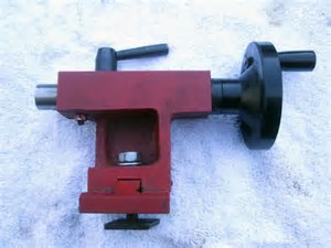
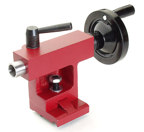
THE TAILSTOCK
TIP HOLDER MOUNTED TO TAIL CHUCK AND THEN TIP RUN UP AGAINST THE FERRULE. THE THREE SCREWS HAVE BEEN ADJUSTED TO CENTER A 14MM TIP ON A 13MM FERRULE. NOTE THE USE OF A DELRIN COLLET PROTECTING THE WOODEN SHAFT. THE THREE SCREWS ARE TIGHTENED AGAINST THE SIDES OF THE TIP ONLY ENOUGH TO JUST HOLD THE TIP. LATER ON I STARTED USING FRACTION SIZE TIPS SUCH AS A 13.5MM TIP FOR A 13MM SHAFT OR A 13MM TIP FOR A 12.75MM SHAFT. I FOUND THAT THE CLOSER THE SIZE OF TIP IS TO THE SIZE OF THE SHAFT THE LESS THE LEATHER IS DISTURBED WHEN TRIMMING THE SIDES MAKING FOR A MORE EASILY TRIMMED, SANDED AND FIRMER BURNISHING SURFACE. SOME TIPS FRAY ON THE SIDES WHEN TRIMMING THE EXCESS ON THE LATHE ESPECIALLY SOFT TIPS. USING VERY SHARP CUTTING BIT COUPLED WITH A MORE CLOSELY SIZED TIP ELIMINATES THAT
I USE A SET OF THESE CUE SHAFT COLLETS MADE OF DELRIN FOR CHUCKING THE CUE IN THE LATHE - FROM EBAY
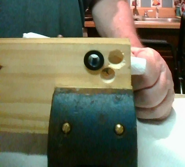
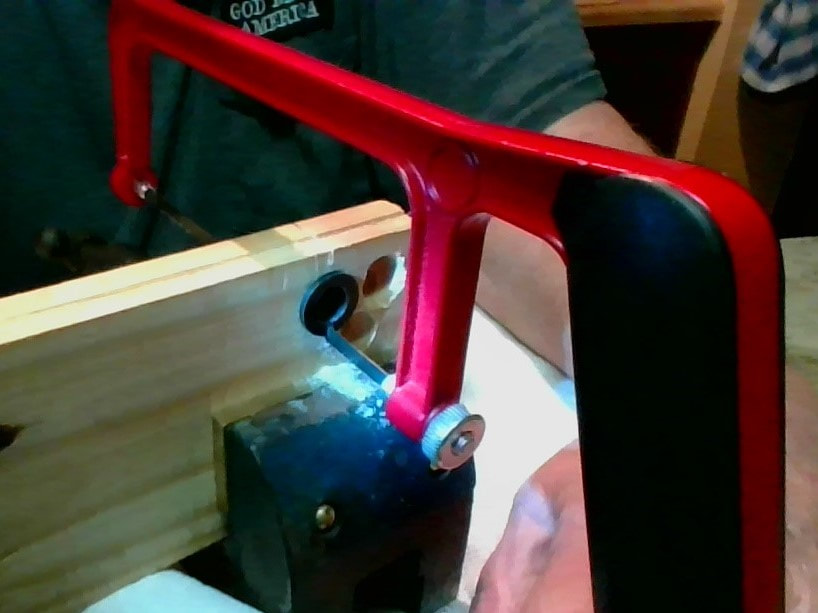
Eventually I made my own collets. Here a Delrin plastic collet that has been turned on the lathe is mounted in a drilled hole in a piece of wood (photo 1) and the slot is cut with a mini-hacksaw (photo 2). To do this the hacksaw blade was removed from the frame and re-mounted with the blade inside the collet. Cutting the slot this way eliminates flashings on the inside of the collet hole. I had started to cut the slot from the outside and the start cut in the wood can be seen in photo 2, but I abandoned that idea for the previous mentioned method. The finished slot cut can be seen in photo 3 for a collet I made for use on an 11 mm cue shaft.

THE TIP GLUE. I use the brand of tip glue that has a rubber additive (Cue Components Tough Tip) and I have found this to be the best and strongest bond. I use the same glue for installing ferrules. While it may begin to over-thicken and solidify over time, I have found that it can be rejuvenated by adding and stirring in a "water thin" fast glue (Cue Components Super Thin Instacure) as is used for seeping into cracks etc. This way I have made the rubberized tip glue to last 2 years or more without placing it in the refrigerator.
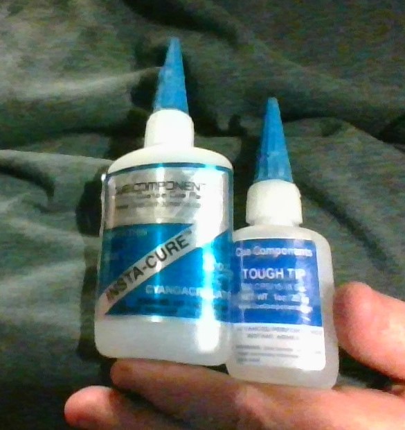
THERE ARE MANY GOOD TIP GLUE BRANDS ON THE MARKET. I HAVE FOUND "TOUGH TIP" (R) TO BE EXCEPTIONAL. INSTA-CURE (L) IS A GREAT WATERY THIN GLUE FOR SEEPING INTO TIGHT PLACES AND I ALSO USE IT TO THIN THE TOUGH TIP GLUE WHEN IT STARTS TO THICKEN FROM AGE. THESE ARE CYANOACRYLATES.
PREPARING THE TIP. It is important that the back of the tip be sanded for a better holding glue job. I use 120 grit first then 220 grit to make a good gluing surface. Also I cover the surface of both the tip and the ferrule with glue.
PREPARING THE FERRULE. It is also important that the face of the ferrule/tenon surface is flat and faced off neatly before tipping. In most cases the lathe bit accomplishes a good face. Sometimes the bit will leave a tit in the center or I might need to sand the face for better glue adhesion. This might be done by hand but to avoid rounding the edge of the face I chuck a tool in the tailstock and with sandpaper held in place I advance the tailstock/tool/sandpaper into the ferrule face to get a smooth face. That tool is a brass diffuser from an old vacuum cleaner. An old valve from a lawnmower engine would work as well if it has a flat head. Also one could be made on the lathe from a hardwood dowel.
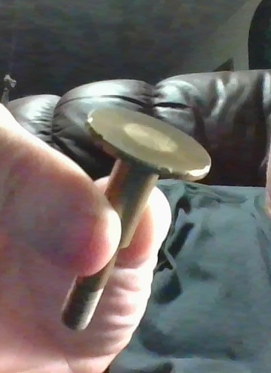
I SOMETIMES USE THIS BRASS DIFFUSER FROM AN OLD
VACUUM CLEANER TO CHUCK ONTO THE TAILSTOCK FOR USING
WITH SANDPAPER TO FACE A FERRULE BEFORE TIPPING
VACUUM CLEANER TO CHUCK ONTO THE TAILSTOCK FOR USING
WITH SANDPAPER TO FACE A FERRULE BEFORE TIPPING

LATHE DIALS. The best feature of a mini-hobby metalworking lathe, is the fine control of the tool bit which can be used to make cuts in miniscule amounts with the in-out or left-right control wheels which have drums that are measurement graduated. Here is where those measurement drums come in handy in this case the one on the in-out wheel. When trimming the tip you can run the lathe bit into the (non-spinning) ferrule and take note of the measurement at the point of contact and then back it out and move it to the front of the tip and take it back in to the same measurement to cut (trim) the tip edge to match the ferrule. I usually back the depth out a few thousandths from the noted ferrule measurement to cut the tip slightly larger than the ferrule and finish trimming the tip (to match the ferrule) with sandpaper held to a board (or sanding block). IMPORTANT: The graduations on my lathe are not accurate. For example, a radial cut of .1mm reading the dial gives me an actual result of .15 mm. A radial cut of .004" on the dial gives me an actual cut of .0045. Do not trust the dial readings on these lathes until you have tested them. I use the graduations only for reference points. Replacement kits are available and I eventually installed the 20 Turns Per Inch kit form Littlemachineshop.com. (P/N 2383 Feed Screw Parts, 20 TPI $59.95). I found this upgrade to be extremely accurate.
LATHE GRADUATED DIAL ON THE CONTROL WHEEL......
GREAT FOR PRECISION TRIMMING OF TIPS AND FERRULES
I use the graduations only for reference points as they are inaccurate.
This is an unfortunate shortcoming in some of these inexpensive lathes.
Some come correct but mine did not. Kits are available to correct this issue.
UPDATE: I installed the 20 TPI kit to correct the problem. Write up is at end of this site.
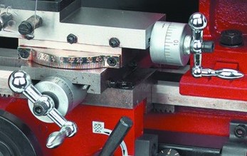
IMAGE SHOWING BOTH PRECISION CONTROL WHEELS WITH GRADUATED DIALS.
LEFT: IN-OUT CONTROL. (OR CROSS SLIDE) RIGHT : RIGHT-LEFT CONTROL (COMPOUND OR TOOL SLIDE)
LEFT: IN-OUT CONTROL. (OR CROSS SLIDE) RIGHT : RIGHT-LEFT CONTROL (COMPOUND OR TOOL SLIDE)

THE CUTTING BIT STOCK. At this point I would like to mention the cutting bits I use. I have been using the 5/16" square X 2 1/2" long HSS (High Speed Steel) blanks which I grind myself and I have my grinder rests set for the correct angle for shaping the cutter tool blank to the desired configuration. I went on the internet to familiarize myself with shapes and methods of grinding steel cutting bits and applied these principles to make mine to my own satisfaction. My main bit for trimming tips and ferrules, cutting tenons and facing off the ferrule is a right to left cutter configuration. I use a left to right configuration for re-facing joints according to the method I use as will be discussed farther down on this document. Cobalt bits are harder and will require less sharpening. I have recently purchased a 5% cobalt bit but have not used it as yet. holders with replaceable bit inserts are popular and eliminate grinding your own.
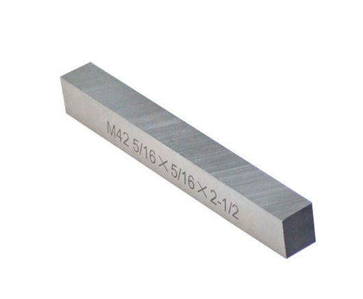
LATHE BIT BLANK FOR GRINDING YOUR OWN BIT
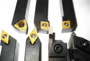
BIT HOLDERS WITH REPLACABLE BITS AVOIDS GRINDING
Various instructions for LATHE TOOL GRINDING can be found on the internet which are
helpful but for cutting wood, plastic and leather more simplified cutters can be made.
helpful but for cutting wood, plastic and leather more simplified cutters can be made.
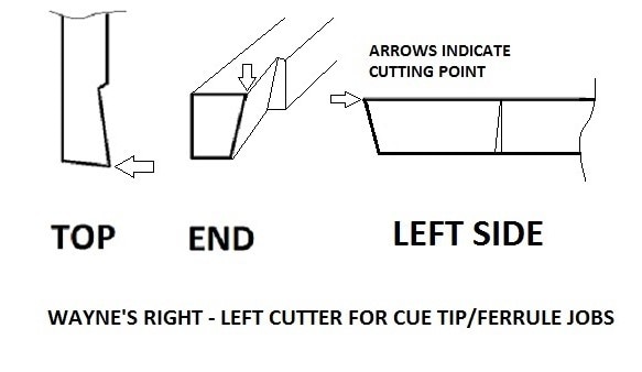
Diagram showing how I grind the 5/16 x 5/16 x 2 1/2 bit blank to make a right to left lathe cutting
bit which is excellent to my liking for cutting cue tips and ferrules or shaft tenons. etc. The tool must
be able to reach to the middle of a 14mm ferrule so I make the side grind back into the blank @ 3/8" or so.
The reason for this is that after continued re-sharpening the ledge that forms does not run into my work
when facing a ferrule. You will notice that this bit, having only two grinding surfaces, is simpler
than the one in the previous diagram which is intended for metal cutting. However I later found it advantageous to grind another bevel on the top increasing the cutting edge to a sharper angle. The angles are simply made by adjusting the grinder rest and letting the curvature of the rock do the rest.
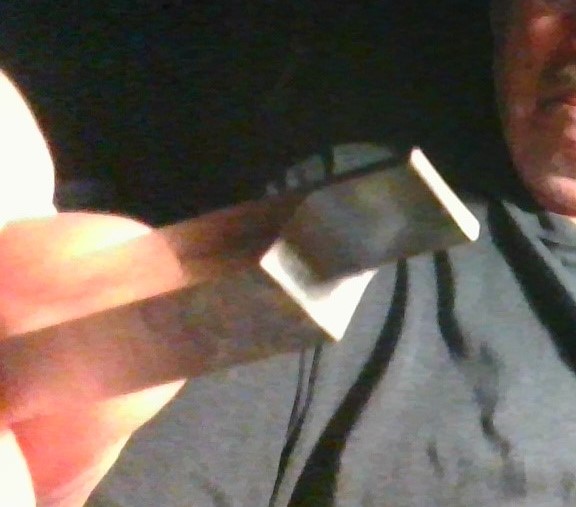
HERE IS A RIGHT TO LEFT CUTTING BIT (NOW RETIRED) THAT I USED FOR A LONG TIME AND HAS BEEN RE-SHARPENED SO MANY TIMES UNTIL THERE IS A DEEP LEDGE. THE CUTTING POINT IS THE FAR RIGHT INSIDE POINT. I AM HOLDING THE BIT UPSIDE DOWN. THE CLEARANCE IS ONLY @ 5/16" WHICH IS ENOUGH TO FACE A 5/8" DOWEL. JUST ENOUGH TO FACE A 14MM FERRULE. YOU CAN SEE THAT THE ANGLES ON THIS BIT ARE VERY SLIGHT COMPARED TO THE DIAGRAM. MY NEXT BIT IS ANGLED A LITTLE MORE THAN THIS ONE.
GAUGING SHAFTS AND FERRULES. Another convenience I recommend is the use of a machinist gauge when chucking the cue shaft to center the shaft or ferrule true in the chuck. I use a gauge and magnetic base purchased from Harbor Freight sold separately but totaling only $23.00 and it is surprisingly of good quality. This is very helpful in trimming the tip evenly to the ferrule because it eliminates wobble or camming. I use the very popular Delrin lathe collets purchased on ebay as a set for $50.00 (well worth it) for chucking the cue shaft into the lathe. I have a three jaw chuck on my lathe and I can usually readjust the center by loosening the chuck and putting finger pressure on the ferrule or cue end in the desired direction and retightening, then rechecking gauge for center. I usually get it true with just a couple of adjustments. For more difficult shaft centering I use paper to shim between chuck and collet which can take some experimentation with different paper thicknesses or folds. While this is a delicate task it makes a HUGE difference in a doing good job and saves time in the long run. A four jaw chuck with individual jaw adjustments would be a luxury here. Eventually I installed a four jaw chuck with independent jaw adjustment is a luxury item which makes for precise true centering and wondered why I didn't do it sooner.
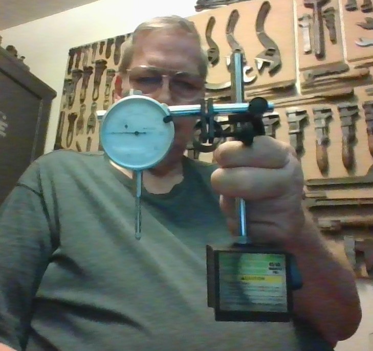
HARBOR FREIGHT GAUGE AND MAGNETIC MOUNT COMBO
USING THE GAUGE WITH THE MAGNETIC MOUNT ATTACHED TO THE CROSS SLIDE BEHIND THE TOOL REST
THE CHUCK IS ADJUSTED FOR ZERO DEFLECTION OR AS CLOSE A POSSIBLE WITHIN A COUPLE OF THOUSANDTHS
OF AN INCH WHEN THE CHUCK IS ROTATED BY HAND. THIS HELPS IN CUTTING AND TRIMMING TRUE AND FLUSH.
THE CHUCK IS ADJUSTED FOR ZERO DEFLECTION OR AS CLOSE A POSSIBLE WITHIN A COUPLE OF THOUSANDTHS
OF AN INCH WHEN THE CHUCK IS ROTATED BY HAND. THIS HELPS IN CUTTING AND TRIMMING TRUE AND FLUSH.
TIP SHAPING. For soft tips and layered tips I shape the tip to a nickel radius with 120 grit paper held to a wooden backing board followed by 220 grit and sometimes 320 grit if the tip is very soft. For hard tips I use a shaper purchased on ebay that mounts to the lathe bit holder. This cutter, while great for hard tips, tends to loosen the leather fibers on soft tips and can separate layers on cheaper layered tips, which is why I use sandpaper for shaping these.
FERRULE SANDING. When all lathing is finished I am ready to sand the ferrule/tip to a polish. Making sure ALL lathing is completed, I loosen the chuck and slide the shaft in till the wood is covered by the collet. This prevents sanding the wood. If there is still a mismatch between tip and ferrule, I use 220 grit held to a board to finish the edge of the tip flush to the ferrule as needed, then I sand tip and ferrule with several grades of sandpaper 220, 320, 600, 1200, and 2000 grit using strip of sandpaper wrapped around the ferrule/tip and held together at the ends with the fingers. Some people may find up to 600 grit satisfactory enough but for personal cues I want a better than new shine which 2000 grit will give. I use sandpaper in packages of 9" X 11" full sheets bought at Lowes which I cut with scissors into sanding strips 1 1/2 inch wide (+ or -) or whatever size is needed. Some ferrules may not need sanding with the heavier grit. If they are free of scratches and other blemishes, they can be cleaned before tipping with Mr. Clean Magic Eraser pads. Then, after tipping they can be polished with 600, 1200 and 2000 grits. If sanding with heavier grits can be avoided, the ferrule diameter will be maintained for many more re-tips.
BURNISHING AND FINAL POLISHING. Burnishing the side of the tip makes for a good appearance but also strengthens the tip edge and helps guard against mushrooming. After sanding the ferrule and tip to a polish I then burnish the leather edge of the tip by applying a wet fingertip of spit or a Q-tip dipped in burnishing dye to the side of the tip while turning it slow and then burnish with an old leather belt held around the tip (in the same manner as using sandpaper) at high lathe speed for 15-20 seconds or as needed for a nice shiny burnished leather finish. With burnishing dye I found it best to mask the ferrule from the tip with easy release painter's tape to avoid having to clean the dye from the ferrule. Burnishing hard Le-pro tips work well with spit but soft Elkmaster tips work best with a burnishing dye. After burnishing the tip I apply cue polish with a paper towel to the ferrule and side of the tip at slow lathe speed and polish at high lathe speed with cloth from an old cotton T-shirt. The finished job looks better than new. You can seal the ferrule and side of the tip with shaft sealer instead of wax.
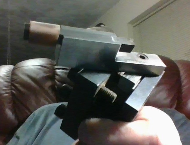
THIS PHOTO SHOWS MY LATHE TOOL HOLDER. IT ROTATES FOR QUICK CHANGING DIFFERENT TOOLS. ON THIS SIDE I HAVE MOUNTED A "CUE MAN" TIP SHAPING TOOL WHICH IS PICTURED IN THE UP POSITION. THE BIT IS ADJUSTABLE FOR TIP RADIUS WITH TWO SMALL ALLEN SET SCREWS. THE LARGE ALLEN SCREW SHOWN IS THE PIVOT AXIS. I HAVE THE TOOL SHIMMED FOR CENTERPOINT HEIGHT AND THE SHIM EDGE IS VISIBLE. I USE THIS FOR HARD TIPS, PREFERRING TO USE SANDPAPER FOR SHAPING SOFT TIPS AND LAYERED TIPS. FOUND ON THE INTERNET. QUICK CHANGE TOOL POSTS ARE AVAILABLE WHICH ELIMINATE SHIMMING OF THE BITS WITH HOLDERS HAVING HEIGHT ADJUSTMENT SCREWS.
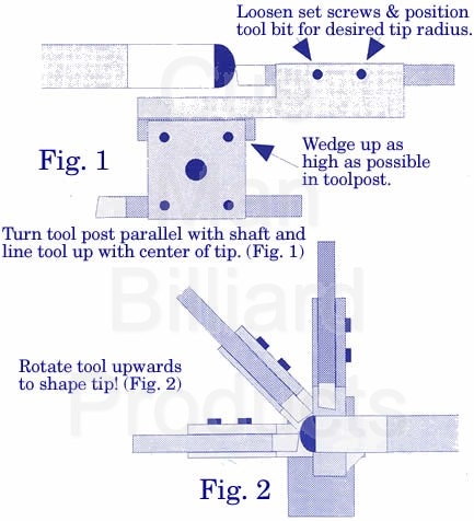
THE "CUE MAN" AUTOMATIC TIP SHAPER. FOUND AT:
https://www.cuesmith.com/automatic-tip-shaper.html
https://www.cuesmith.com/automatic-tip-shaper.html
THE LATHE TOOL HOLDER SHOWING THE RIGHT TO LEFT CUTTING BIT ON THE RIGHT. AS FOR THE BIT, YOU CAN SEE THAT I CHANGED THE GRINDING ANGLE ON THE BIT END. I USED THE COARSE STONE TO MAKE THE LOWER ANGLE GRIND AND THE FINE STONE TO MAKE THE UPPER ANGLE GRIND. THE BACKSIDE MOUNTING OF THE "CUE MAN" TIP SHAPING BIT IS SEEN ON THE LEFT SIDE OF THE TOOL HOLDER AND THE TWO TIP RADIUS ADJUSTING ALLEN SET SCREWS ARE VISIBLE AS WELL. THE FACE OF THE TIP SHAPER CUTTER IS ALSO VISIBLE, LOWER LEFT CORNER. BOTH TOOLS ARE SHIMMED TO BRING THE TOOL POINTS TO THE LATHE CENTER. A QUICK CHANGE POST ELIMINATES SHIMMING (BELOW).
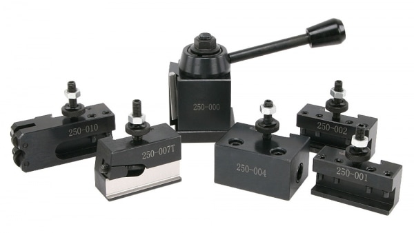
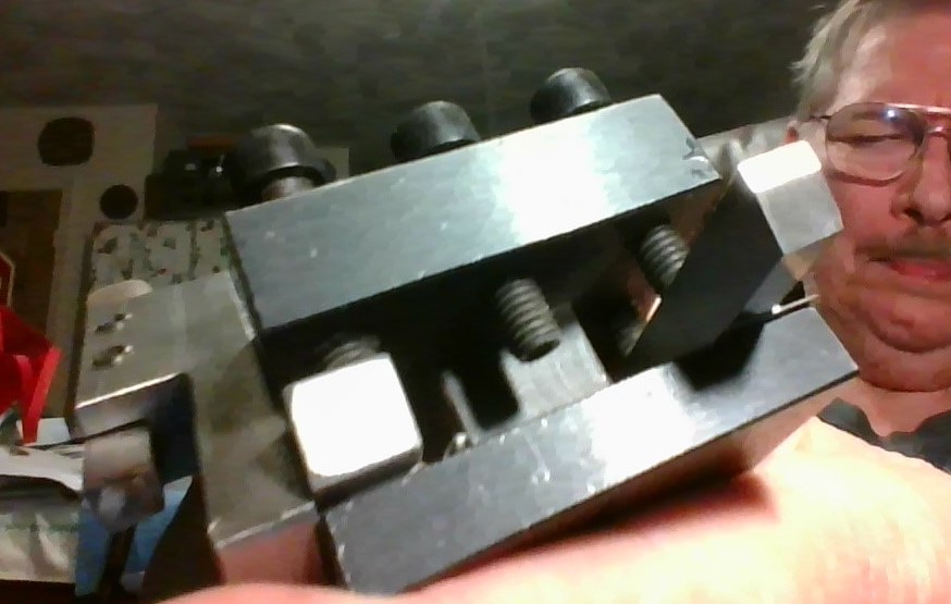
THE QUICK CHANGE TOOL POSTS AND HOLDER KITS ALLOW TOOLING WITHOUT SHIMS AND ARE A GREAT UPGRADE FOR THE MINI-LATHE. AVAILABLE IN PISTON OR WEDGE LOCKING MECHANISMS THE WEDGE IS THE STURDIER BUT MORE EXPENSIVE. THEY ARE MADE OF ALUMINUM OR STEEL IN VARYING PRICES AND MODELS TO FIT MOST LATHES. SHOWN IS A WEDGE TYPE QUICK CHANGE KIT OXA SIZE 000 MADE OF STEEL FROM LITTLE MACHINE SHOP MODEL 3112. I EVENTUALLY UPGRADED MY LATHE WITH THE OXA AND MADE LIFE MUCH BETTER.
CUE WAX - USE FOR FINISH POLISHING FERRULES AND SHAFTS. GREAT FOR THE ENTIRE CUE.
THE MINI-LATHE... ADAPTING FOR CUES USING OUTRIGGERS AND ROLLER RESTS. The Harbor Freight lathe I use for cue tip and ferrule work costs only $500.00 and it competes well against the multi-thousand dollar cue lathes. I added wooden outriggers to which roller rests are mounted which I found on ebay. Rail extensions would be ideal but expensive. I use an outrigger on each end and a total of three roller rests. For the outrigger behind the spindle end I use one roller rest for house cues and another one closer in for shafts. For the outrigger on the tailstock end I use one roller rest for turning shafts for sanding, resizing and polishing. I also use this one for re-facing shaft joint faces and butt joint faces.
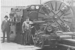
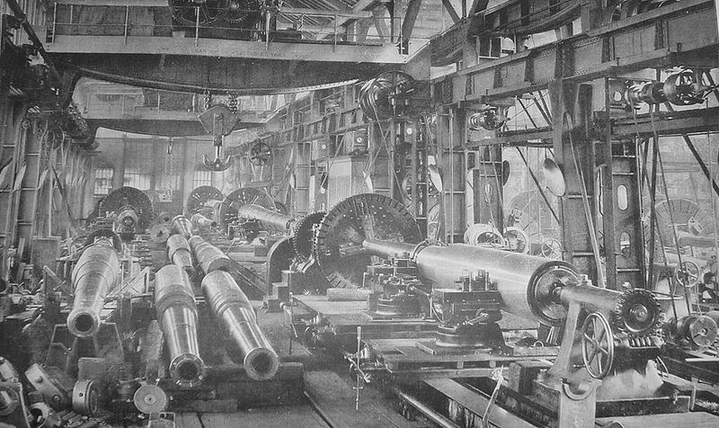
HMMM . . . I HAVE A LATHE HERE SOMEWHERE . . .
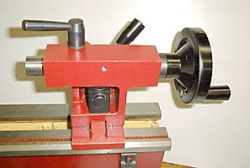
THE HARBOR FREIGHT LATHE WITH THE SPINDLE END OUTRIGGER SHOWING THE ROLLER REST IN PLACE (FOREGROUND) FOR TURNING HOUSE CUES. ONLY THE SHAFT END OF A CUE WILL FIT THROUGH THE 3/4" LATHE SPINDLE. THE ROLLER REST FOR USE WITH PERSONAL CUE SHAFTS CAN BE SEEN STORED BEHIND THE OUTRIGGER. THE DELRIN COLLET SET CAN BE SEEN STORED NEATLY ON PINS FOR EASY ACCESS. HOLES DRILLED IN-LINE ON THE SILL CAN BE SEEN WHICH ARE USED FOR MOUNTING THE ROLLER RESTS. OBJECTS ON THE SILL ARE A MAGNIFYING GLASS, CUE WAX SANDPAPER STRIPS HANDLED PICKS, ROLL OF PAINTER'S TAPE, FLAT DISC TIP SCUFFER, LEATHER BURNISHING PAD. BELOW ON THE 2X12 BOARD I HAVE DRILLED HOLES FOR THREE ALLEN WRENCHES, T-HANDLED LATHE CHUCK WRENCH, TAIL CHUCK WRENCH, A THROWING DART FOR CLEARING GLUE SPRUES IN GLUE CONTAINERS, AND THERE IS A JEWELER'S LOUPE HIDDEN UNDER THE SILL AS WELL AS CANS CONTAINING VARIOUS PINS, SHAFT ARBORS HOMEMADE COLLETS AND ABOUT ANY OTHER SMALL ARTIFACT IMAGINABLE. A 1X4 PIECE OF PINE CAN BE SEEN AGAINST THE LATHE BEHIND THE MAGNIFYING GLASS FOR USE AS A SANDING BOARD. I KEEP LATHE CUTTERS, CENTERS, CALIPERS, GUAGES, BITS, ETC IN A WOODEN HARBOR FREIGHT MACHINIST TOOL BOX. THE OTHER OUTRIGGER (NOT SHOWN) HAS THE TIP TOOL. POCKET KNIFE, AND WHATEVER ON IT. UNDER THE SILL IN AN OLD WOODEN BOX IS GLUE, SHAFT SEALER, LIQUID TIP BURNISHING DYE, MEDICINE BOTTLES CONTAINING Q TIPS, TOOTHPICS, RAZOR BLADES, STRAIGHT PINS AND LOTS OF OTHER STUFF. THE DRAWER IS FULL OF TOOLS AND EVERYTHING IMAGINABLE AND NEEDED FOR WHATEVER. THE SHELVES HAVE BOXES OF TIPS, FERRULES, PINS, DOWELS, A CRAFTSMAN SOCKET SET, LATHE BOOK AND WHO KNOWS WHAT ELSE. WALLS IN THIS ROOM ARE COVERED WITH ANTIQUE TOOLS AND IMPLEMENTS.
HERE IS ONE OF MY ROLLER RESTS. I PURCHASED THESE ON EBAY. THEY OFFERED CUSTOM MADE IF DESIRED FOR MORE HEIGHT. I BUILT MY OUTRIGGER WOODEN RAILS TO WORK WITH THE ROLLER RESTS I BOUGHT.
ALIGNMENT OF THE ROLLER RESTS. I aligned my roller rests at first with a rod attached to the lathe chuck and got them pretty close but a rod is somewhat droopy. I could have done better with a piece of 1/2 copper pipe. Then I had a brainstorm and bought one of those Chinese bore lights which has the shape of a cartridge so it will fit in a rifle of whatever caliber you choose. I put the bore sight in the lathe but I had to wrap tape around one end (I anticipated this because cartridges are tapered) turning on the laser before chucking. The bore sight worked well. For exact roller rest centering I will place a 1" length of dowel the diameter I want to use and place it in the rollers as a target, and adjust the rollers for center on the dowel face. The chuck is rotated to check for centering and if the laser is off center line the laser dot will circle/rotate on the target (because I used tape around the sight it is not exact in the chuck). If so it can still be used to center the rollers just by getting the dot to circle a dot marked on the center of the target. This gets the roller rest spot on for the work being turned, which in my case is cue shafts or cue butts, and I then mark the frame on each support for the 3 different diameters I will be using most so I can return to those settings without re-sighting. I have sighted the rests at the tailstock end and also the rests at the spindle end (shooting the laser through the spindle bore). There may be some perfectly cylindrical sights that will work without taping and may have a switch on them and these would be better. But this one is cheap costing 5 bucks.
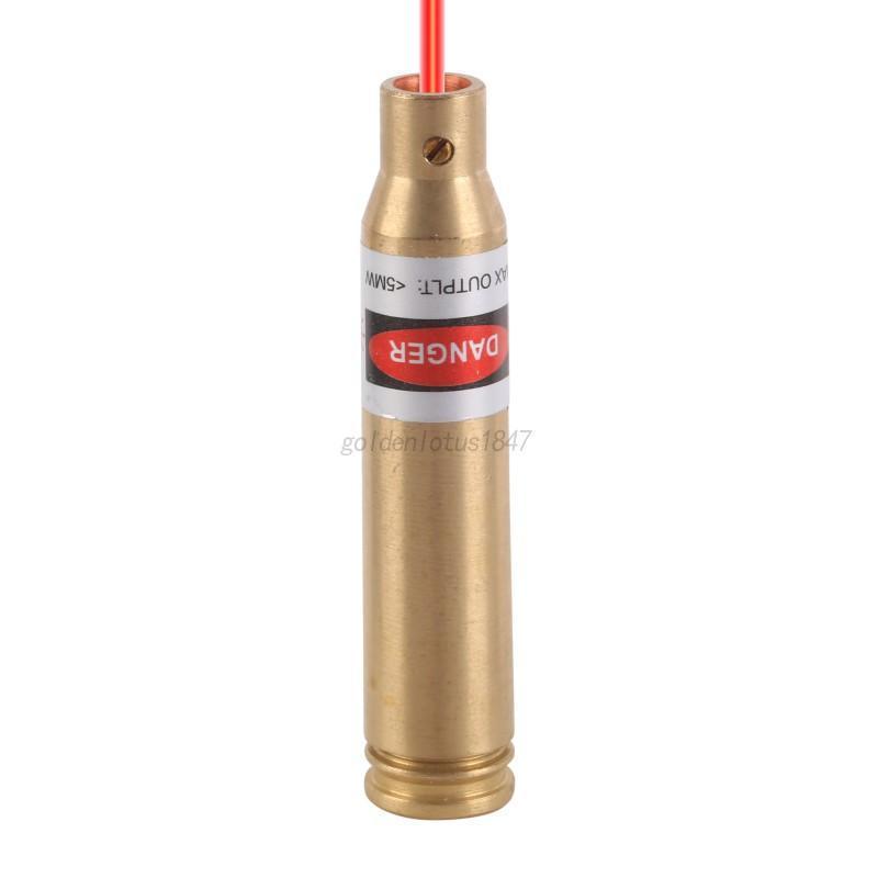
HERE IS AN EXAMPLE OF THE LASER BORE SIGHT I PURCHASED ON EBAY.
THE BASE UNSCREWS AND THREE BATTERIES ARE INSERTED AT THE CORRECT POLARITY.
TIGHTENING THE BASE BACK ON TURNS ON THE LASER.
BACKING THE BASE OFF A COUPLE OR SO TURNS WILL TURN THE LASER OFF.
THE BASE UNSCREWS AND THREE BATTERIES ARE INSERTED AT THE CORRECT POLARITY.
TIGHTENING THE BASE BACK ON TURNS ON THE LASER.
BACKING THE BASE OFF A COUPLE OR SO TURNS WILL TURN THE LASER OFF.
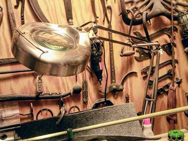
A GOOD LAMP ON A FINE SUSPENSION ARM IS A MUST. I USE
ONE WHICH HAS A MAGNIFIER. THIS COMES IN HANDY.
ONE WHICH HAS A MAGNIFIER. THIS COMES IN HANDY.

THE LATHE IS MOUNTED WITH SCREWS THROUGH THE BASEPLATE HOLES (WHERE THE RUBBER FEET WOULD HAVE GONE) TO A PIECE OF 2 X 12 PINE LUMBER WHICH SITS ON A HOMEMADE ONE DRAWER TWO SHELF PLYWOOD CABINET. THE 2X12 IS HELD ON THE TOP OF THE CABINET WITH TWO C-CLAMPS IN THE BACK. THE OUTRIGGERS ARE 2 X 4 PINE LUMBER WHICH ARE ATTACHED TO THE 2 X 12, EACH WITH WASHERS AND THREE LAG SCREWS (HOLES IN THE 2 X 12'S ARE SLOTTED TO ALLOW ADJUSTING ALIGNMENT) . ON TOP OF THE 2X4'S THE SHELVES ARE EACH ATTACHED WITH SEVERAL 2" SHEETROCK TYPE SCREWS. THE SHELVES ARE CUT FROM 1X6 FIR WINDOW SILL STOCK. HOLES ARE DRILLED IN A LINE DOWN THE SPINDLE AXIS IN THE SILL TO MOUNT THE ROLLER RESTS FOR VARYING DISTANCES. THE LATHE SPINDLE HOLE CAN BE SEEN IN THIS PICTURE 1/4 DOWN FROM THE TOP NEAR THE LEFT EDGE OF THE PHOTO. NOT SEEN BEHIND THE LATHE IS A SWITCHED OUTLET STRIP MOUNTED TO THE 2X12 SO EVERYTHING CAN BE TURNED ON WITH A SINGLE SWITCH. PLUGGED INTO THE POWER OUTLET STRIP IS THE LATHE, A DREMEL MOTOR AND A LAMP. THE DREMEL MOTOR IS HANGING ON THE WALL AND THE LAMP , WHICH IS A MAGNIFIER LAMP WITH A SENSITIVE MOVING ARM, IS MOUNTED TO THE OTHER END OF THE 2X12. PART OF THE LAMP ARM IS VISIBLE BEHIND THE TAILSTOCK AND PART OF THE LAMP HEAD CAN BE SEEN INTRUDING FROM THE TOP CENTER EDGE OF THE PHOTO. THOSE ARE MY KEYS ON THE FLOOR.
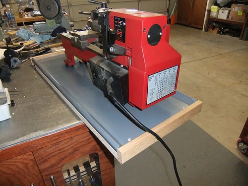
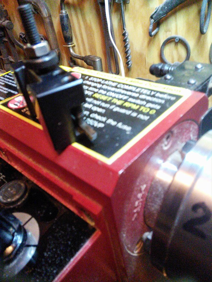
IMAGE OF THE SPINDLE END OF A NEW LATHE JUST OUT OF THE BOX. THAT BLACK DISK HELD BY TWO SCREWS IS THE SPINDLE COVER. THIS COVER NEEDS TO BE REMOVED BECAUSE THAT IS WHERE THE CUE SHAFTS ARE INSERTED AND THE TIP END COMES OUT THROUGH THE CHUCK WHICH IS ON THE OTHER SIDE
HERE YOU CAN SEE THE HEAD END (CHUCK END) OUTRIGGER SHOWING A CUE SHAFT WITH TIP END INSERTED INTO THE SPINDLE TO THE CHUCK AND THE JOINT END SECURED BY THE ROLLER REST. NOTE THAT THE JOINT END IS PROTECTED FROM THE ROLLERS BY A FEW WRAPS OF BLUE PAINTER'S TAPE. I HAVE ARBORS WHICH THREAD INTO THE JOINT AND THE ARBOR CAN BE PLACED IN THE ROLLERS WHICH AVOIDS USING TAPE BUT THIS SHAFT HAS A RADIAL PIN THREAD FOR WHICH I DON'T HAVE AN ARBOR. ALSO A JOINT PROTECTOR CAN BE USED AS AN ARBOR.
|
|
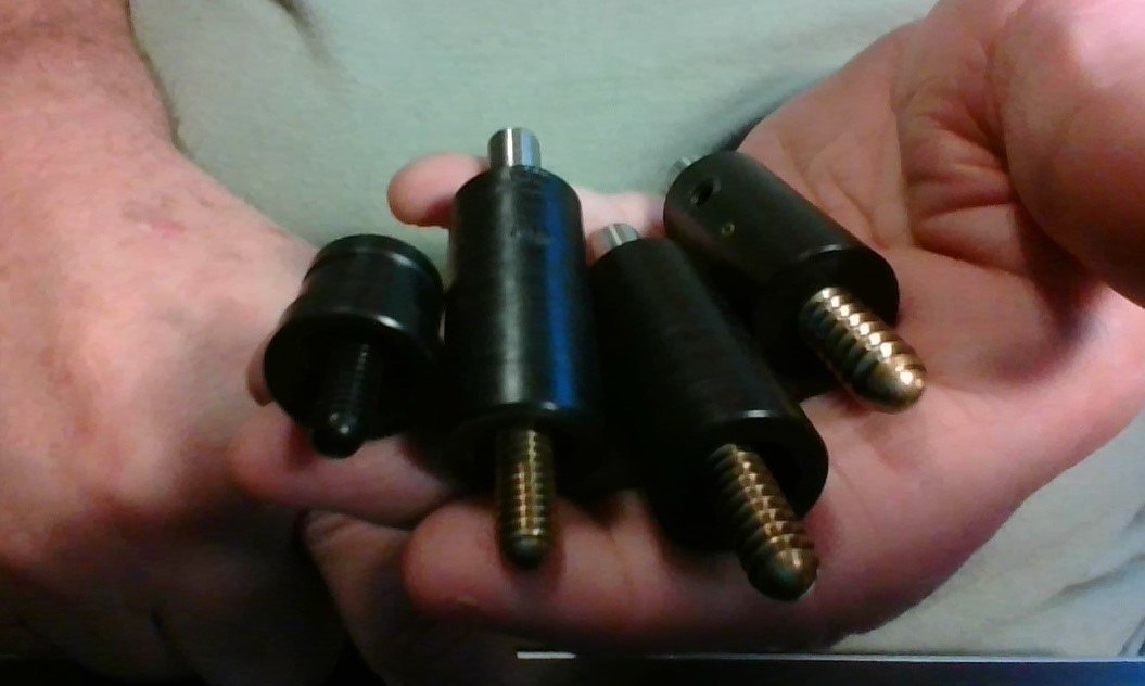
HERE I AM HOLDING A SET OF THREE ARBORS (FOUND ON EBAY) FOR USE IN THE JOINT END OF CUE SHAFTS. A 3/8 X 10, 5/16 X 14, AND A 5/16 X 18. THESE CAN BE USED TO SUPPORT THE JOINT END OF THE SHAFT IN THE ROLLER REST. ALSO A JOINT PROTECTOR (ON THE LEFT IN RIGHT PHOTO) CAN BE USED AS AN ARBOR.
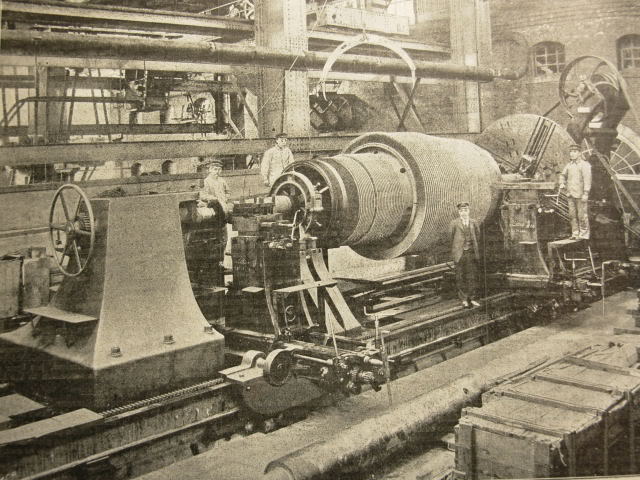
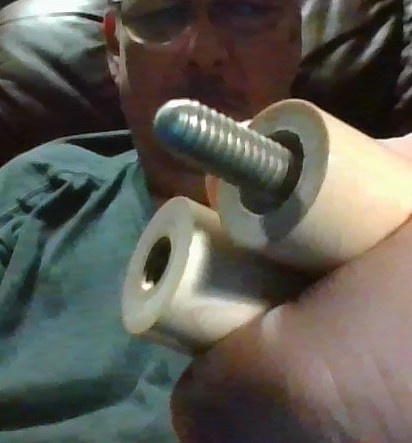
HMMM.....THINKING ABOUT BUILDING POWERFUL BREAK CUES
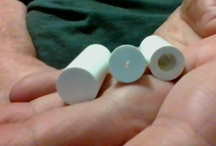
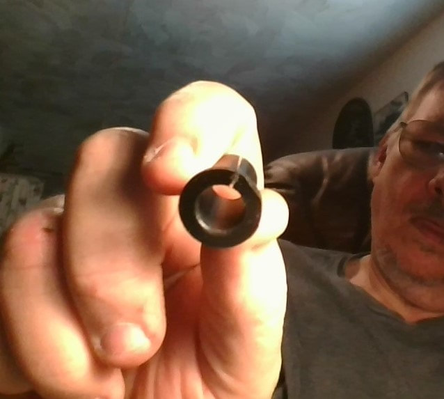
L to R.... FERRULE BLANK ....CAPPED FERRULE .... OPEN ENDED FERRULE
REPLACING FERRULES. I use my mini-lathe setup to remove and replace ferrules. Here is where center truing the shaft with a gauge is MOST important. If the cue was originally made true the tenon will be true to center and the cutter blade can remove the old ferrule exactly to the tenon. I cut the old ferrule a little depth at a time usually making 4-6 passes before I reach near the tenon. Then I experiment with fitting the new ferrule by shaving a little at a time from the first 1/4th inch of the tenon end until I attain a ferrule fit and then cut the rest of the length of the tenon to the shoulder. This avoids overcutting and undersizing the tenon and accomplishes a snug fit of the ferrule to the tenon. It is also necessary to face the shaft at the base of the tenon for a good seat. Then with some slow glue applied to the tenon and a drop or two inside the back end of the new ferrule the new ferrule can be inserted (slightly turning it, I have even pushed them on with the lathe turning at a slow rate) and then the cutter blade can be locked against the front end of the ferrule to hold it tight till the glue sets. This is done by locking the feed arm and turning the left-right wheel on the tool holder to push the side of the bit against the end of the ferrule. After the glue is set the ferrule can then be trimmed on the end flush to the end of the tenon and then trimmed almost to the diameter of the shaft. I always leave a little and cut the rest with the tip after the tip is installed. The tip can then be applied and when set both the tip and ferrule can be trimmed together to match the shaft diameter by using the in-out tool wheel with its measuring drum to determine depth to match to the depth to the shaft minus a few thousandths as is my rule. This is done in a similar manner as the way I matched the tip to an already existing ferrule as mentioned earlier except in this case the initial measurement is taken at the shaft behind the ferrule. When I trim the tip and ferrule together I run the lathe at high speed and use the right to left control wheel for the tip, then, not changing the cutting bit depth, I slow the lathe speed and continue in to trim the ferrule with the main control wheel. After the new ferrule and tip are lathed even to the shaft diameter (less a few thousandths) the sanding can then be done. In this case I start with 320 grit or 600 grit instead of 220 grit because the ferrule is already very smooth. For house cues the lathe cut finish is good enough and I don't do any finish sanding unless requested by the customer or, for example, if it is an antique house cue.
AVOIDING SANDING THE WOOD SHAFT. When all cutting and tip shaping is done, before sanding the ferrule, the cue wood can be protected by readjusting the position of the shaft in the lathe chuck to bring the back edge of the ferrule right up to the front edge of the collet so that all the wood is covered by the collet. Again, All cutting and tip shaping should be completed before shifting the wood under the collet because the center truing will be affected when re-chucking. Another method is to mask the wood with painter's tape and this method does not require re-chucking the shaft and thereby retains the true center in case additional cutting or shaping is found necessary. Anytime the wood IS sanded for whatever reason, the bare wood should be coated after sanding with one or two applications of shaft sealer being careful to avoid getting sealer on the ferrule (or clean the sealer off the ferrule). Then the wood can be polished with cue wax along with the ferrule. Some cue repair people put sealer on the ferrule, but I prefer to wax the ferrule.
AVOIDING SANDING THE WOOD SHAFT. When all cutting and tip shaping is done, before sanding the ferrule, the cue wood can be protected by readjusting the position of the shaft in the lathe chuck to bring the back edge of the ferrule right up to the front edge of the collet so that all the wood is covered by the collet. Again, All cutting and tip shaping should be completed before shifting the wood under the collet because the center truing will be affected when re-chucking. Another method is to mask the wood with painter's tape and this method does not require re-chucking the shaft and thereby retains the true center in case additional cutting or shaping is found necessary. Anytime the wood IS sanded for whatever reason, the bare wood should be coated after sanding with one or two applications of shaft sealer being careful to avoid getting sealer on the ferrule (or clean the sealer off the ferrule). Then the wood can be polished with cue wax along with the ferrule. Some cue repair people put sealer on the ferrule, but I prefer to wax the ferrule.
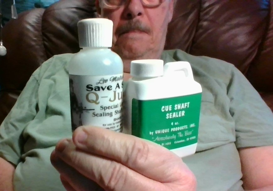
SHAFT SEALER SHOULD ALWAYS BE USED WHEN SHAFTS ARE SANDED. I USE IT WHEN THERE IS A SANDED PORTION IN THE WOOD AFTER SANDING A FERRULE BUT USUALLY I AVOID THIS BY COVERING THE WOOD WITH THE COLLET AFTER LATHING AND BEFORE SANDING. I USE IT EXCLUSIVELY WHEN RESANDING WHOLE SHAFTS OR SANDING A CUE TO A CUSTOM PRO-TAPER OR A SMALLER DIAMETER. THERE ARE MANY VARIETIES ON THE MARKET.

REMOVING FERRULES WITH OFF CENTER TENONS. A cheap cue with an off-center tenon presents a different problem. Looking at the end where you can see the eccentric wood tenon in the ferrule I usually chuck the shaft off center to match the off center tenon so the shaft wobbles when spinning but the tenon is true. Then I can lathe cut the old ferrule away and retain the off-center tenon intact. After installing the new ferrule the shaft needs to be trued to center in the chuck again before installing the tip and trimming tip and ferrule to the shaft diameter (minus a few thousandths in depth). A note here on lathe chucks: The three jaw scroll chuck is great for quick self centering but objects must be shimmed for exact center accuracy when such accuracy is needed. Also when off axis chucking is desired large shims must be employed. Later I purchased a four jaw independent chuck and I use it exclusively. Set up is time consuming but worth it and eliminates the need to shim which is more time consuming.
|
|
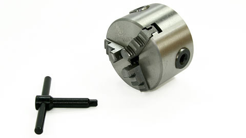
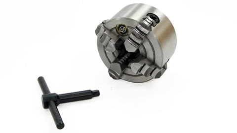
LATHE CHUCKS. ON THE LEFT IS THE THREE JAW "SCROLL" CHUCK WHICH COMES ON THE MINI LATHE. THE SCROLL CHUCK HAS JAWS WHICH ALL MOVE TOGETHER CONCENTRICALLY AND IS THUS SELF CENTERING. ON THE RIGHT IS THE FOUR JAW CHUCK WHICH CAN BE PURCHASED WITH SCROLL SELF CENTERING JAWS OR INDEPENDENTLY ADJUSTABLE JAWS. THE PHOTO SHOWS A 3" INDEPENDENT 4 JAW CHUCK FROM LITTLEMACHINESHOP.COM. I EVENTUALLY UPGRADED MY LATHE TO THIS CHUCK AND IT MADE LIFE BETTER.

BROKEN TENONS. If the tenon is damaged or broken you can cut a new tenon from the shaft with the lathe bit, but of course this ends up with a shorter than original shaft length. There is an alternative. I have made a 5/16" dowel about 2 1/2" to 3" long to use as a new tenon which will result in retaining the original shaft length. The remains of the old tenon are removed from the shaft by using the lathe bit to face off the end of the shaft. Then a centering bit is used in the tailstock chuck to make a shallow centering hole at the end of the shaft followed by @ 1/8" or 3/16" drill bit to desired depth and then a 5/16" drill bit can be used to drill the finish hole to the desired depth, a depth perhaps equal to the length of a ferrule plus 1/4" or so. If you have a 5/16" forstner bit, that can be used to square off the bottom of the hole. Then a good slower glue or epoxy can be used and the new 5/16" dowel inserted to become a new tenon. The glue needs to be thin enough to allow trapped air to be released as the tenon dowel is pushed home and it may even be necessary to score a thin groove for this purpose along the length of the dowel at least along the dowel to a length past the depth of the hole. There are tools available for threading the tenon hole and installing threaded tenons. I am not a professional and do not desire to make my hobby a career but these methods can be found on internet videos and are worth looking into.
THREADED FERRULES. I usually replace threaded ferrules with standard ferrules. I only replace with threaded ferrules when the threads on the tenon can be cleaned of the old glue and even that takes a lot of work. I keep a set of picks and a hook blade knife and some small wire tooth brushes such that are used for gunsmithing to do this but only if the old glue is very brittle. Often the wood threads will break or even the threaded tenon will break off part or all of the tenon at a thread. I do not have the luxury of a rotary thread cutter and I don't even want to get into that. If my customer HAS TO HAVE threaded ferrules they must see some other dude. Threading a tenon can be done by hand or on the lathe with a tenon compression die and is an interesting concept but the BEST method is with a thread mill bit on a tool grinder motor attachment mounted to the tailstock. These advanced methods can be expensive but a good way to go if it is a career thing. Another point to consider, threaded ferrules are capped ferrules and this means the tenon is too short for a full standard open end ferrule. So if the threaded tenon is covered with a standard open end ferrule the excess ferrule must be cut off to meet the end of the tenon. This is acceptable for some customers and many new low deflection shafts have even shorter ferrules. I have made my own standard ferrules with caps from ferrule blanks which will solve the short replacement problem if desired. One other solution is to lengthen the tenon by cutting the shaft down and use a standard open ended ferrule and I have done this also if the customer is happy with that. Another solution is instead of cutting the end of the ferrule down to the end of the tenon, the hole left can be filled with epoxy, but I do not know how this might affect the feel of the hit.

|
THE PRO-TAPER (OR PROFESSIONAL TAPER) SHAFT. Standard house cues and many personal cues are made with conical taper shafts. The shaft increases in diameter steadily from ferrule to joint or forearm. The pro-tapered shaft has a constant diameter from the ferrule to halfway up the shaft then begins to increase in diameter at a rate based on a curve which reaches a point where it becomes conical near the joint. The advantage of the pro-taper is that the part of the shaft which is bridged by the hand retains a constant diameter so as the bridge fingers grip the cue loosely the fingers retain their hold without flexing outwards during the stroke and inwards during the back stroke as would occur with a conical shaft.
DIAGRAM (EXAGGERATED FOR CLARITY) ILLUSTRATING THE DIFFERENCE
BETWEEN A PRO-TAPER AND A CONICAL TAPER CUE SHAFT. THERE ARE MANY SHAFT DESIGNS THAT LIE BETWEEN THESE EXTREMES. 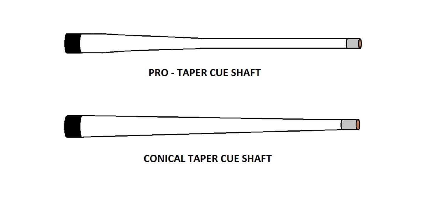
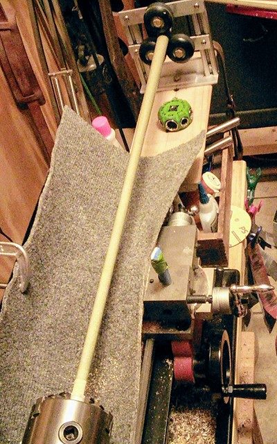
RE-SIZING A SHAFT, AND/OR CHANGING THE TAPER. PART 1. Occasionally someone will want me to re-size a 13mm or 12.75mm shaft to 12 to 12.25 mm shaft, and provide a pro-taper to the shaft as well. Resizing is a time consuming process with the method I use (using sandpaper) so one must be dedicated and have a good eye to perform this task. A tapering machine would be nice but expensive just to size and taper one to two shafts per year which is about my workload for this job.
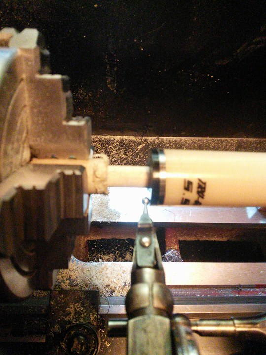
I begin by gauging the ferrule and adjusting the chuck to center the shaft as described in an earlier paragraph; see " GUAGING SHAFTS AND FERRULES". I chuck the shaft with about 2 1/2 inches extending out from the collet, as seen in the photo and I lathe the end of the shaft, ferrule and tip to the desired diameter by first cutting a slight radius from the tip and part of the ferrule, measuring with a caliper, re-cutting and re-measuring until I get to the desired diameter and then cut the rest of the ferrule and an inch of the shaft with that diameter. If you like using the dial graduations for this that's fine, but I will stick to my method. The reason for starting with just part of the ferrule is that you can replace the ferrule if you go too deep but you can't replace the wood. One could even just cut at the tip to key to the desired diameter. 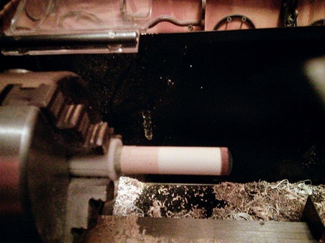
HERE THE SHAFT END, FERRULE AND TIP HAVE BEEN RESIZED WITH THE LATHE BIT TO THE DESIRED NEW DIAMETER. THE SHAFT IS THEN REMOVED FROM THE SPINDLE AND THE SHAFT IS REPOSITIONED INTO THE CHUCK FROM THE FRONT FOR SANDING.
IN THE PROCESS OF REVERSING THE SHAFT BUT BEFORE INSERTING INTO THE CHUCK. THE COLLET COVERS THE FERRULE TO PROTECT THE FERRULE FROM SANDING AT THIS TIME. YOU CAN SEE THE LEDGE WHERE THIS 12.5 MM SHAFT HAS BEEN CUT TO 12 MM ON THE FERRULE END WITH THE LATHE BIT AND THE BURR WOOD EDGE HAS BEEN TRIMMED.
|
THIS ILLUSTRATES THE FERRULE TIGHTENED INTO THE FRONT END
OF THE CHUCK WITH THE COLLET JUST COVERING THE FERRULE.
OF THE CHUCK WITH THE COLLET JUST COVERING THE FERRULE.
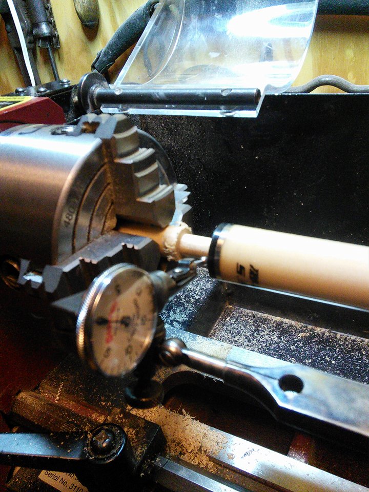
HERE IS ANOTHER VIEW OF THE FERRULE PLACED IN THE FRONT END OF THE CHUCK SHOWING THE JOINT END PLACED IN THE ROLLER REST AT THE TAIL END OF THE OUTRIGGER. THE TAIL STOCK HAS BEEN REMOVED FROM THE RAIL AND THE TOOL HOLDER HAS BEEN REMOVED FROM THE TOOL SLIDE. THE TOOL HOLDER MOUNTING STUD HAS BEEN COVERED WITH A PAPER TUBE I MADE TO KEEP THE THREADS CLEAN. I HAVE PLACED A PIECE OF CARPET ON THE LATHE BED TO CATCH THE SANDING DUST. YOU MAY NOTICE THE GREEN MULTI-SOCKET TOOL I FOUND AT HARBOR FREIGHT WHICH I USED FOR UNBOLTING THE ROLLER RESTS AND MOVING TO THE DESIRED HOLE AND WHICH HAS MANY OTHER USES.
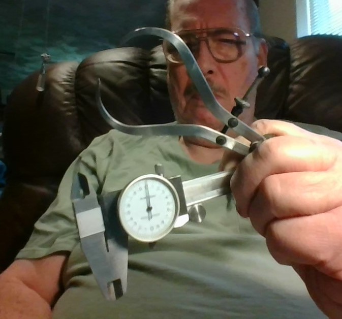
CALIPERS. THESE ARE A MUST FOR RESIZING/RESHAPING SHAFTS. I DO NOT START WITHOUT THEM.
RE-SIZING A SHAFT, AND/OR CHANGING THE TAPER, PART2. With the end of the shaft cut to desired size and then the shaft repositioned into the front end of the chuck as shown in the above two illustrations, the sanding can begin. With the lathe turning at high speed the shaft is sanded beginning with 120 grit paper to bring the rest of the shaft to the proper taper and reduce the shaft to almost match the lathed diameter which was cut earlier. Avoid sanding the part that was cut with the lathe. Then progressive finer grits of 220 grit and 320 grit are used to match to the precut diameter, still avoiding sanding the part that was cut with the lathe. Then 600 grit, 1200 grit and 2000 grit are used to finish the shaft to a polish all the way to the edge of the ferrule including the part that was cut by the lathe.
It takes a good eye coupled with the use of calipers to properly re-size/re-taper a shaft by hand. It is important to stop and observe carefully as well as measure your progress at frequent intervals because you can ALWAYS sand wood off but you can NEVER put wood back. I have re-sized and re-tapered shafts successfully and to precision by taking my time. The first one I did was just as good as the last one I did, as were all those in between. My friends were very pleased and they showed it by running the rack with their customized shafts.
It takes a good eye coupled with the use of calipers to properly re-size/re-taper a shaft by hand. It is important to stop and observe carefully as well as measure your progress at frequent intervals because you can ALWAYS sand wood off but you can NEVER put wood back. I have re-sized and re-tapered shafts successfully and to precision by taking my time. The first one I did was just as good as the last one I did, as were all those in between. My friends were very pleased and they showed it by running the rack with their customized shafts.
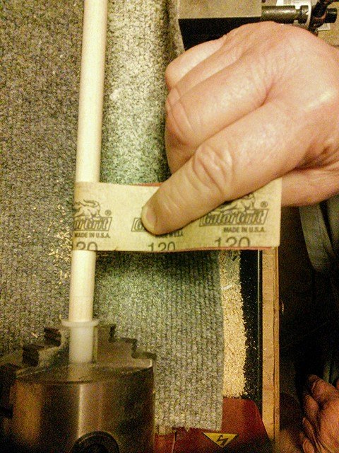
ILLUSTRATION : METHOD OF HOLDING THE SANDPAPER STRIP WHILE SANDING THE SHAFT AT HIGH SPEED. AVOID SANDING THE LATHE CUT PORTION UNTIL YOU MATCH THE DIAMETER AND REACH THE FINER GRITS 600 - 2000. THE STRIPS ARE + OR - 2" WIDE AND THE LENGTH OF THE FULL SHEET. AS THE GRIT WEARS I SHIFT TO A FRESH PORTION OF THE STRIP AS NEEDED.
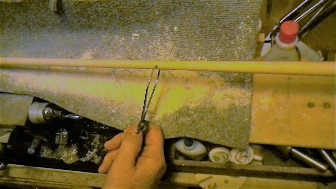
FIRST, GET THE DESIRED SHAPE. HERE I HAVE SANDED THE SHAFT WITH 120 GRIT PAPER TO THE PRO-TAPER SHAPE. THE CALIPERS ARE HELD AT THE POINT WHERE THE SHAFT DIAMETER BEGINS TO INCREASE WHICH IS 14 1/2" FROM THE TIP END OR EXACTLY HALF OF THE LENGTH OF THIS 29" SHAFT. FROM THE CALIPER TO THE LEFT OF THIS PAGE THE DIAMETER OF THE SHAFT IS THE SAME, THUS ESTABLISHING THE PRO-TAPER. TO THE RIGHT OF THE CALIPER THE SHAFT IS TRANSITIONED SMOOTHLY TOWARD THE JOINT. NOW THAT THE DESIRED SHAPE IS ESTABLISHED I WILL SAND TO REDUCE THE DIAMETER TO THE DESIRED SIZE, WHILE MAINTAINING THE PRO-TAPER SHAPE.
RE-SIZING A SHAFT, AND/OR CHANGING THE TAPER, CONTINUED PART 3. With all the shaft sand polished then two applications of shaft sealer can be wiped onto the shaft. I apply one application with a piece of cotton cloth, let it dry and then apply a second application. I apply the shaft sealer with the lathe turning the shaft at a slow rate for an even application.
When the shaft sealer is dry I check for smoothness. Sometimes the sealer will raise some tiny splinters. You can't see them but you can feel them. I sand these out with 2000 grit paper (with lathe running at high speed) or buff it out with a shaft slicker buffer followed by a leather pad without removing the sanding sealer. Sometimes just the buffer or the leather pad alone is enough. One might prefer some very fine steel wool like 00 or 000 (double or triple aught) fine. Sometimes this isn't a problem at all after using sealer
Next I wax the cue by turning the lathe slow and applying Q-WAX with a paper towel and then buffing at high speed with a piece of old t-shirt. The more sophisticated individual might use a polishing cloth. The results are the same except old t-shirts are free. After wax polishing I burnish lightly at high lathe speed with a leather pad.
When the wood is polished the shaft is then removed and re-inserted into the chuck through the spindle, with the wood covered by the collet. Then the ferrule and tip can be sanded and the tip burnished. Then the tip and ferrule can be wax polished.
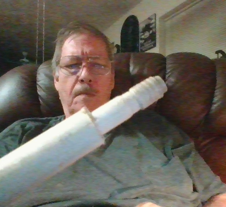
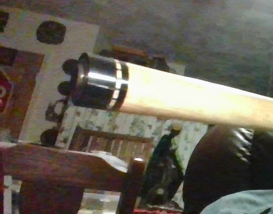
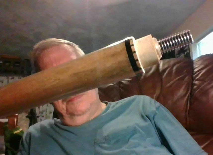
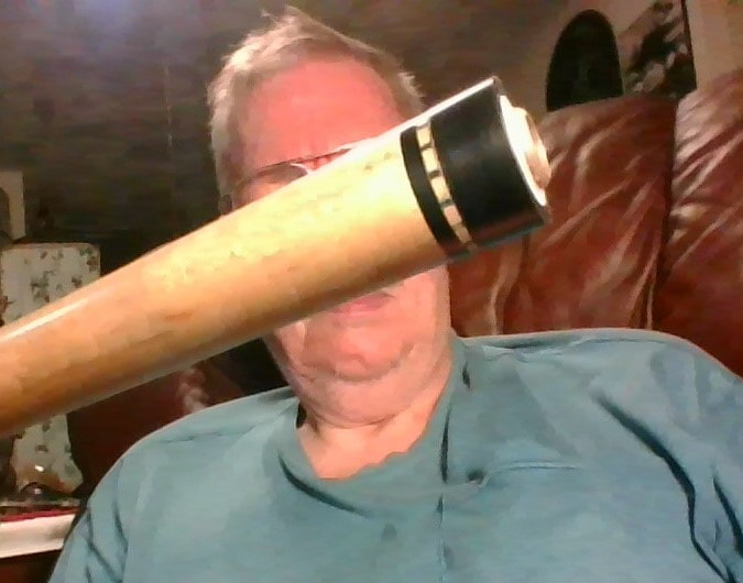
THE TASK COMPLETED. THE SHAFT HAS BEEN RESIZED TO 12MM AND RESHAPED TO A PRO-TAPER.
THE SHAFT BEGINS TO TAPER MIDWAY, AT THE POINT BELOW MY RIGHT EYE. FROM THERE TO
THE TIP THERE IS NO CHANGE IN THE SHAFT DIAMETER. THIS SHAFT IS A DALE PERRY STAGE IV AND
COST $150.00 SO IT WAS IMPORTANT THAT I KNEW WHAT I WAS DOING WHEN I TOOK ON THE JOB.
THE SHAFT BEGINS TO TAPER MIDWAY, AT THE POINT BELOW MY RIGHT EYE. FROM THERE TO
THE TIP THERE IS NO CHANGE IN THE SHAFT DIAMETER. THIS SHAFT IS A DALE PERRY STAGE IV AND
COST $150.00 SO IT WAS IMPORTANT THAT I KNEW WHAT I WAS DOING WHEN I TOOK ON THE JOB.
REFACING THE JOINT....WHY REFACE THE JOINT? Age can cause slight warpage in a favored cue which throws the joint face off from 90 degrees to the axis. This can happen to the butt or the shaft. If the joint faces are not true there will be an off axis kick right at the joint as seen by looking down the cue. Warps further away from the joint may throw only the tip off axis. The tip will be seen running off the axis as one looks down the cue. If the butt is slightly warped or the shaft is slightly warped these effects can be minimized (but not completely cured of course) by re-facing the joint of the offending member. Extreme warps are a loss and attempts to straighten them are futile. I have tried using flex jigs and the warp just ends up coming back. It is NEVER a good practice to leave a cue in a hot car in the sun in summertime. This is probably the most common reason cue shafts and butts become warped. Improper curing of the wood before cue manufacture is another cause. Very slight warps do not mean throw a favored or expensive cue away. Re-facing the joint(s) is a rewarding alternative. Why re-face the joint? If you have a cue which has a kick at or very near the joint, then facing one or both joint faces will "fix" it (i.e. minimize the effects). Any bends far away from the joint cannot be "fixed" but their effects can still be minimized by re-facing. My everyday cue is a used older high grade Meucci Model 97-21 with a red dot shaft which lists for $580.00 but I bought for $30.00 because you could look down the axis and there was a kick at the joint and when rolled showed a terrible wobble. After re-facing the joint faces the cue looks straight, rolls straight and shoots straight.
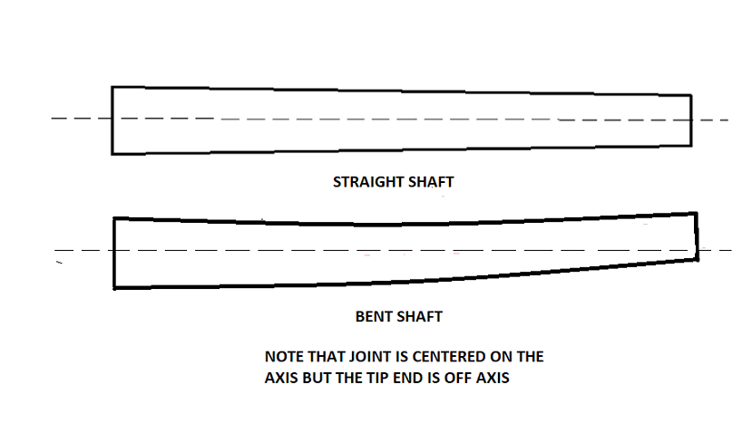
(EXAGGERATED FOR CLARITY) THIS DIAGRAM ILLUSTRATES A STRAIGHT SHAFT AND ONE THAT IS WARPED. THE JOINT FACE IS 90 DEGREES AND CENTERED TO THE AXIS ON BOTH. THE TIP ON THE STRAIGHT SHAFT IS ALSO CENTERED ON THE AXIS BUT ON THE WARPED SHAFT THE TIP HAS DRIFTED OFF AXIS AND IS NO LONGER CENTERED.
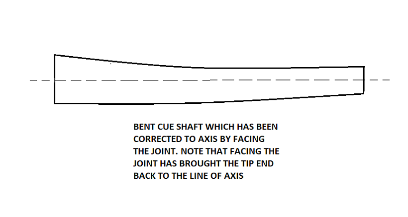
IN THIS ILLUSTRATION THE WARPED SHAFT HAS BEEN REFACED TO BRING THE AXIS TO CENTER ON BOTH THE JOINT AND THE TIP, ALTHOUGH THE BODY IS OFF AXIS DUE TO THE WARP. FACING THE JOINT MINIMIZES THE EFFECTS OF THE WARP AND IS REOMMENDED ONLY ON SHAFTS THAT HAVE A MINIMAL WARP. SEVERELY WARPED SHAFTS OR BUTTS ARE A LOSS AND REFACING THEM IS A WASTE OF TIME.
WHICH JOINT SHOULD BE REFACED? I can look down the length of a cue and see warps which do not show so well when the cue is rolled. the tip will show a turn to the side when eyeing it with the dominant eye just above the butt bumper. Turn the cue and the tip will turn to one side then the other. I have marked warped shafts with a dot at the point when the tip turns straight up or straight down and have used these cues with excellent results by keeping the dot up when shooting. This eliminates the effect of the warp. Facing the joint eliminates the need for a dot mark on a warped shaft. One way to tell which member (butt or shaft) is warped is to roll each individually to observe the lope. Some have a good eye to see it by eyeing down the butt or shaft independently. Sometimes BOTH butt and shaft are warped.
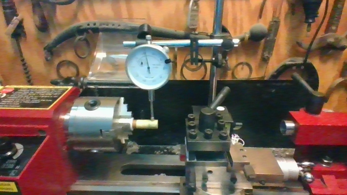
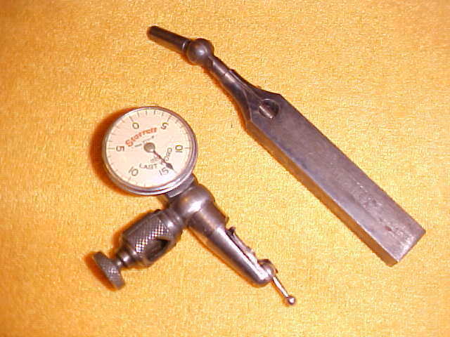
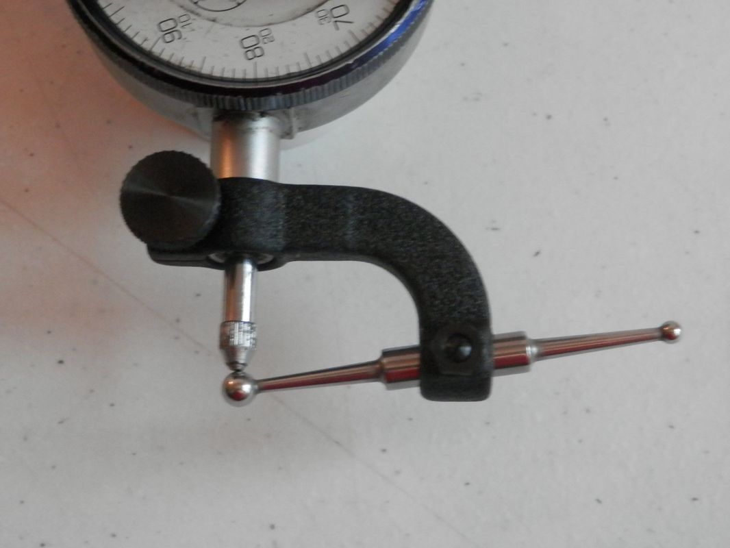
The precise method of detecting the offending member is with the use of a dial test indicator. The suspected butt or shaft chucked in the lathe with the joint end at the chuck and the other end in a roller rest. The butt or shaft is trued to center axis in the chuck with a dial gauge which will place both ends of the butt or shaft on axis and any existing warp will be seen when spun by the lathe. The face of the joint can then be checked by a test indicator. I recently purchased a used Starrett Last Word indicator at a good price which I found to be an excellent and rugged instrument for this purpose. A standard dial gauge just can't get in there unless it has an indicator hole attachment. I tried this with an old Ames 201 set and it was very awkward and time consuming in set-up and still not nearly as good as the Starrett Last Word or other test indicator would be. When the face is checked with the indicator a runout is easily detected if present and with this method it is easy to find the offending member, butt or shaft. After facing the offending member the test indicator shows no deflection indicating a perfect face which to me is very rewarding. Also rewarding is when I screw the butt and shaft together and the tip rolls nicely on axis with the butt, and when I "eye" down the cue the tip doesn't run out. The text below describes how I cut a new joint face.
|
|
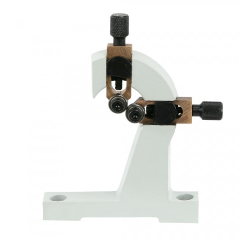
INDICATORS ARE PERFECT FOR READING THE SHAFT FACE FOR RUN-OUT. ON THE LEFT IS THE STARRETT LAST WORD, A LONG TIME FAVORITE FOR THE MACHINIST. A DIAL GAUGE CAN BE USED IF YOU HAVE A HOLE ATTACHMENT (RIGHT) BUT THEY ARE AWKWARD AND TAKE MORE EFFORT TO SET UP, AND STILL QUITE BULKY.
|
|
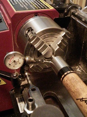
PHOTO ON LEFT: A STARRETT "LAST WORD" DIAL INDICATOR GAUGE IS MOUNTED IN THE LATHE TOOL HOLDER AND IS BEING USED TO READ THE FACE OF A CUE BUTT. THE INDICATOR PIN RESTS ADAINST THE FACE. AS THE LATHE CHUCK IS ROTATED BY HAND THE INDICATOR READS ANY DEFLECTION OFF AN UNTRUE FACE. THIS OLD STEVE MIZERAK SIGNATURE CUE SHOWED A FACE THAT DEVIATED OFF A 90 DEGREE PLANE BY 3/1000 (THREE THOUSANDTHS) OF AN INCH. WHILE THE WARP IN THE BUTT WAS TOO SMALL TO SEE AND SEEMS INSIGNIFICANT AND CAUSED NO PROBLEM AS FAR AS THE BUTT WAS CONCERNED, THIS SMALL DEVIATION IS MAGNIFIED BY LENGTH AND WITH A SHAFT ATTACHED IT THREW THE TIP VISIBLY OFF THE CUE AXIS . PHOTO ON RIGHT: LATHE BIT JUST FINISHED A REFACE CUT. I REFACED THE BUTT JOINT BY REMOVING 5/1000 (FIVE THOUSANDTHS) OF AN INCH FROM THE FACE AND RECHECKED THE DEFLECTION WHICH WAS THEN ZERO. WHEN I RE-ATTACHED THE SHAFT THE TIP WAS RIGHT ON AXIS AGAIN. NOTE THAT I AM USING A FOUR JAW INDEPENDENT CHUCK WHICH FACILITATES CENTERING. ALSO I HAVE CHUCKED THE STAINLESS STEEL PIN DIRECTLY IN THE CHUCK. UNLESS THE CHUCK IS REALLY JACKED DOWN HARD ON THE PIN IT DOESN'T HARM THE THREADS. THE CHUCK IS TIGHTENED ENOUGH TO SECURE THE PIN FIRMLY. IF THIS MAKES YOU QUEASY I SUGGEST A HOMEMADE PLASTIC OR BRASS COLLET TO PROTECT THE PIN THREADS. A ROLLER REST SUPPORTS THE OTHER END OF THE BUTT. PAINTERS TAPE IS USED ON THE BUTT TO PROTECT IT FROM THE ROLLERS.
RE-FACING THE JOINT. Joint ends are commonly between 13/16" to 7/8" diameter and therefore do not fit through the 3/4" spindle of my mini lathe so I get around that by chucking the pin of the butt (with a homemade protecting collet if the pin is soft metal like brass) and the other end of the butt rests in the roller rest with about 4-5 layers of painter's masking tape around the butt where it contacts the rollers for protection of the butt finish. The roller rest center must be at the same height and alignment as the chuck center (i.e. on axis) for this work as it should be for any other job. For facing shaft joint faces the tip/ferrule end is protected with tape and placed in the roller rest. I keep different sized pins and screw the correct pin into the shaft and chuck the other end of the pin in the chuck. It is important that the shaft is not stressed when chucking the pin, otherwise you defeat your purpose of re-facing the joint. Some shafts may not have a perfectly on axis insert in which case I have used the homemade collet to allow flexing at the collet to avoid flexing the shaft. Re-facing must be done by cutting only a sliver at a time down to the chucked pin. A sharp tool bit is also a necessity. Heavy cuts and dull bits could cause rotation of the pin in the chuck or the cue causing a disastrous overbite into the face before binding.
HERE I HAVE A 5/16 X 14 JOINT PIN PURCHASED FROM A CUE BUILDER SUPPLY. I HAVE MADE A COLLET FOR THIS PIN FROM A FERRULE BLANK. I ONLY USE A COLLET WHEN I CANNOT AVOID FLEXING THE SHAFT WHEN CHUCKING IN THE LATHE. A LONGER COLLET MAY BE NECESSARY TO HELP AVOID THREAD SLIP . THE COLLET IS DRILLED AND THREADED INSIDE, AND TURNED TRUE ON THE LATHE . NOTE THAT I HAVE MADE A RIDGE IN THE CENTER. THE PURPOSE FOR THE RIDGE IS SO THAT WHEN PLACING THIS ATTACHED TO A SHAFT IN THE CHUCK WITH THE FERRULE END IN THE ROLLER REST, THE SHAFT IS NOT FLEXED IN THE PROCESS. IT IS IMPORTANT THAT THE SHAFT "FLOAT" IN ITS UNFLEXED UNSTRESSED STATE WHEN RE-FACING THE JOINT, OTHERWISE THE PURPOSE FOR REFACING THE JOINT IS DEFEATED AND THE SHAFT WILL STILL BE MISALIGNED. FLEXING THE SHAFT IS AVOIDED BY HAVING A SMALL AREA OF THE COLLET IN CONTACT WITH THE JAWS OF THE CHUCK. ALSO THE PIN MUST BE BOTTOMED AND TIGHTENED SECURELY IN THE JOINT WITH PLIERS AND THE COLLETT MUST REST TIGHTLY AGAINST THE SHAFT BUSHING TO PREVENT THREAD SLIPPING WHICH WOULD CAUSE THE TOOL TO BITE. I HAVE ALSO USED THIS COLLET ON THE BUTT PIN FOR FACING A BUTT JOINT WITH A BRASS PIN. A BRASS COLLETT MIGHT WORK BETTER. FOR STAINLESS STEEL PINS I CLAMP THE VERY END OF THE PIN DIRECTLY INTO THE CHUCK WITH ONLY THREE THREADS INSIDE THE JAWS. THESE PINS ARE STAINLESS STEEL AND I HAVE NEVER DAMAGED THE THREADS BY DOING THIS, BUT IF THERE IS SOME DAMAGE IT CAN BE CHASED OUT WITH A THREADING DIE, AT LEAST FOR A 5/16 X 18 PIN. FOR OTHER PINS IT MAY BE HARD TO FIND A THREADING DIE. I HAVE BEEN PLANNING TO MAKE A METAL COLLET FOR THIS PURPOSE TO REPLACE THE PLASTIC ONE. THIS WILL AVOID HAVING THE PIN THREADS IN THE CHUCK AND WILL HAVE LESS TENDENCY TO SLIP AND WILL ACCOMODATE A SOFTER BRASS PIN. FOR ODD THREADS LIKE FOR EXAMPLE A RADIAL PIN I WOULD PROBABLY MAKE A LONGER COLLETT WITHOUT INSIDE THREADS AND CLAMP IT TIGHTLY. THIS WOULD AVOID PURCHASING AN EXPENSIVE RADIAL TAP. ANOTHE RMETHOD I HAVE USED TO AVOID SHAFT FLEX FROM CHUCKING IN THE LATHE IS TO USE A LONG PIN AND LET THE PIN FLEX INSTEAD OF THE SHAFT. KEEP IN MIND THAT THERE WILL PROBABLY ALWAYS BE SOME FLEX IN THE SHAFT AND EXPERIMENTATION MAY BE NECESSARY TO FLOAT A SHAFT WHEN CHUCKING INTO A LATHE. I HAVE FACED SHAFTS AS MANY AS THREE ATTEMPTS BEFORE I GOT IT RIGHT. ALL PREVIOUS ERRORS BECAUSE OF UNDESIRED SHAFT FLEXING DUE TO THE CHUCK ACTION IN TIGHTENING THE CHUCK JAWS. (THIS TOPIC IS STILL UNDER CONSTRUCTION ON MY SITE.... MORE COMING LATER)
FACING A SHAFT JOINT WHEN YOU DON'T HAVE A PIN. Today I needed to check the face of an S.S.T. TRU-GLIDE shaft with the Cuetec joint threads because even though the shaft appeared straight and rolled by itself without a wobble, when it was joined to the butt I could see a slight rollout of the tip when eyeing down the full cue. The Cuetec cue uses a 3/8 X 14 thread. The common threads for 3/8" are 3/8 X 16 and 3/8 X 24. To get a 3/8 X 14 pin would be a special order if I could find one. Instead I took a 1/2" wooden dowel, chucked it in the lathe and adjusted with a gauge to center it in the chuck. Then I cut the end of this dowel down to where I could thread the shaft onto the dowel without damaging the plastic threads in the SST shaft but tight enough to hold the shaft for facing. Again the tip end of the shaft was in the roller rest and protected with painter's tape. This method was very successful.
|
|
THESE PHOTOS SHOW AN S.S.T. TRU-GLIDE SHAFT HELD IN THE LATHE BY A DOWEL WHICH HAS BEEN CUT DOWN TO ALLOW THE SHAFT TO BE THREADED ONTO THE BARE UNTHREADED DOWEL BECAUSE A PIN WAS NOT AVAILABLE. THE STARRETT INDICATOR HAS BEEN BROUGHT TO THE FACE OF THE SHAFT AND DETECTED A .002" (TWO THOUSANDTHS OF AN INCH) DEFLECTION OFF THE PERPENDICULAR PLANE. THE SHAFT WAS THEN FACED WITH A LEFT TO RIGHT CUTTER BIT AND .004" OF THE FACE WAS REMOVED. UPON RECHECKING WITH THE INDICATOR GAUGE THERE WAS NO DEFLECTION AND WHEN THE SHAFT WAS SCREWED ONTO THE CUE IT WAS VERY CLOSE. THEN I CHECKED THE BUTT AND IT WAS OFF TRUE ABOUT .0015. AFTER FACING THE BUTT JOINT FACE THE CUE JOINED TOGETHER WAS STRAIGHT WITH NO INDICATION OF A TIP ROLLOUT.
THIS PHOTO SHOWS THE 1/2" DOWEL THAT WAS CUT DOWN TO THREAD INTO THE SHAFT. I ALSO CUT EACH SIDE OF THE THREADING PART SO THE SHAFT WOULD NOT BE STRESSED BY SIDE FORCES WHICH DEVELOP IN TIGHTENING THE SHAFT ONTO THE DOWEL. THE THREADS IN THE WOOD WERE MADE WHEN THE SHAFT WAS LIGHTLY FORCED/SCREWED ONTO THE DOWEL AND DID NOT AFFECT THE PLASTIC THREADS IN THE SHAFT AT ALL BECAUSE IT WAS CUT CLOSE TO THE I.D. OF THE THREADS. WOOD MAY NOT WORK WELL FOR SHAFTS WITH BRASS INSERTS UNLESS MODIFIED WITH A BOTTOMING OUT IN THE SHAFT. FACING THE BRASS PART WILL CAUSE THE SHAFT TO MOVE ON THE THREADS AND DIGGING OF THE TOOL WOULD RESULT. ABOUT "FLOATING" THE SHAFT.... AS STATED EARLIER, THE SHAFT MUST "FLOAT" IN ITS NATURAL UNSTRESSED STATE WHEN FACING OFF WITH A CUTTING BIT OTHERWISE THE OBJECTIVE OF FACING THE JOINT IS DEFEATED, BECAUSE A STRESSED SHAFT WHEN REMOVED FROM THE LATHE WILL THEN UNSTRESS AND THE JOINT FACE WILL MOVE OFF THE TRUE 90 DEGREE FACE PLANE ACCORDINGLY WHEN REMOVED FROM THE LATHE.
|
|
THE LEFT PHOTO SHOWS THE METHOD I USED TO MOUNT THE STARRETT LAST WORD DIAL INDICATOR TO THE TOOL HOLDER ON THE LATHE COMPOUND REST. THE GAUGE IS ATTACHED TO THE STARRETT UNIVERSAL SHANK WHICH IS ATTACHED TO THE OXA QUICK CHANGE TOOL HOLDER HELD BY TWO OF THE HOLDER'S ALLEN SET SCREWS. MOUNTING THE GAUGE IN THE TOOL HOLDER FACILITATES EASE IN PLACING THE GAUGE PIN TO THE FACE BY USING THE LATHE'S CARRIAGE TRAVEL AND CROSS SLIDE CONTROLS. THE RIGHT PHOTO SHOWS THE BIT IN THE HOLDER (A 1/8" X 1/8" HSS BLANK, GROUND FOR LEFT-RIGHT CUTTING) WHICH WAS USED TO CUT THE FACE OF THE SHAFT. THE BIT IS IN AN OXA QUICK CHANGE TOOL HOLDER. QUICK CHANGE TOOL BIT HOLDERS AND POSTS ARE A MUST HAVE BECAUSE NOT ONLY CAN YOU CHANGE TOOLS WITH THEM IN SECONDS, BUT YOU CAN FINE ADJUST THE HEIGHT OF THE BIT CUTTING POINT TO THE LATHE AXIS WITH THE KNURLED ADJUSTMENT SCREW, WHICH LOCKS WITH A NUT AND SPRING WASHER ABOVE IT. THE OLD TOOL HOLDER THAT CAME WITH THE LATHE REQUIRED THE USE OF SHIMS TO ADJUST BIT HEIGHT.
REPAIRING/REPLACING SHAFT COLLARS. Repairs can be made to cracked shaft collars and plastic butt collars with the mini lathe. As with facing joints shaft or butt collars are repaired by chucking the shaft or butt in the same manner chucking the butt pin and in the case of the shaft, inserting a pin into the shaft and chucking the pin. Again the other end of the part is held in a roller rest protected by painter's tape.
THIS SHAFT HAS A CRACKED JOINT COLLAR. NOTE THAT THERE IS A
DASH DECO RING BEHIND THE COLLAR WHICH MUST BE PRESERVED.
DASH DECO RING BEHIND THE COLLAR WHICH MUST BE PRESERVED.
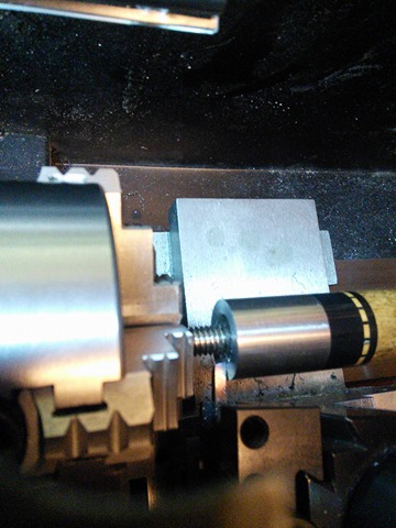
SHAFT AFTER THE COLLAR HAS BEEN REMOVED ON THE LATHE. THE DASH DECO RING WAS PRESERVED WITH THE AID OF A CARRIAGE STOP WHICH PREVENTED CUTTER TRAVEL BEYOND THE EDGE OF THE RING. NOTE THE SHORT LENGTH OF A 5/16 x 18 JOINT PIN BOTTOMED OUT IN THE SHAFT WHICH IS USED TO CHUCK THE SHAFT IN THE LATHE.
MAKING THE NEW SHAFT COLLAR. A one inch diameter delrin plastic dowel was chucked in the lathe and centered. Drill bits were used to make a hole 1/2 inch in diameter and 1/2 inch deep and then a boring bar was used to finish the hole to an inside diameter of 0.635 inch. The use of calipers to measure for a snug fit is necessary. I measured and then made the hole slightly smaller that the finish hole. Then using the shaft and trying inserting it after each bore cut I was able to enlarge the hole a tiny bit at a time until the shaft fit snug. The outside diameter was then cut to the same diameter of the butt collar, 0.840 inch. Then the compound slide was adjusted to 1 degree and the taper was made on the shaft end of the collar to match the outside shaft diameter. Lastly a parting blade was used to cut the finished product from the dowel. snug.
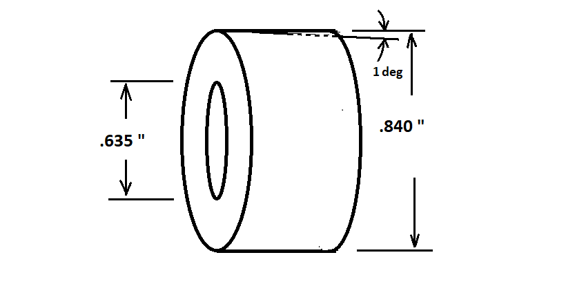
THIS DIAGRAM ILLUSTRATES THE REPLACEMENT SHAFT COLLAR MADE FROM A 1" DELRIN DOWEL. THE INSIDE
DIAMETER IS A SNUG FIT AND WAS ROUGHED ON THE INSIDE WITH 120 GRIT PAPER TO FACILITATE GLUE ADHESION.
THE OUTSIDE DIAMETER WAS MEASURED TO BE EQUAL TO THE DIAMETER OF THE STEEL BUTT COLLAR. THIS .840
OUTSIDE DIAMETER WAS TAPERED ON THE END OPPOSITE THE JOINT FACE BY SETTING THE COMPOUND SLIDE
ANGLE TO 1 DEGREE AND THEN SHAVING THE EDGE AT THAT ANGLE UNTIL THE O.D. ON THE SHAFT END
MATCHED THE O.D. OF THE SHAFT.
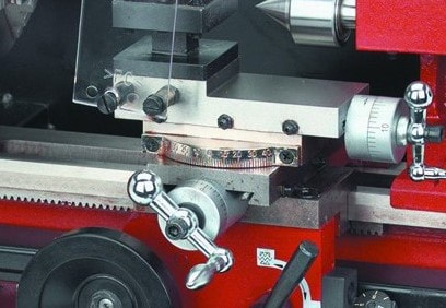
THE HARBOR FREIGHT MINI LATHE HAS A NICELY GRADUATED PROTRACTOR FOR
SETTING THE ANGLE ON THE COMPOUND SLIDE FOR MAKING TAPER CUTS. THE
COMPOUND SLIDE MUST BE BACKED ALL THE WAY OUT TO REVEAL TWO HEX HEAD
CAP SCREWS WHICH ARE LOOSENED TO CHANGE THE ANGLE WHICH OTHERWISE IS
NORMALLY KEPT AT ZERO AS SHOWN IN THIS PHOTO.
SETTING THE ANGLE ON THE COMPOUND SLIDE FOR MAKING TAPER CUTS. THE
COMPOUND SLIDE MUST BE BACKED ALL THE WAY OUT TO REVEAL TWO HEX HEAD
CAP SCREWS WHICH ARE LOOSENED TO CHANGE THE ANGLE WHICH OTHERWISE IS
NORMALLY KEPT AT ZERO AS SHOWN IN THIS PHOTO.
THE COLLAR IS MADE SLIGHTLY LONGER THAN NEEDED. IN THIS PHOTO THE COLLAR
HAS BEEN GLUED IN PLACE AND EXCESS COLLAR LENGTH HAS BEEN TRIMMED. THE
PLASTIC COLLAR AND WOOD HAVE BEEN REFACED DOWN TO THE BRASS BUSHING.
AGAIN WHEN REFACING, THE SHAFT MUST BE UNSTRESSED WHEN CHUCKED IN
THE LATHE OR THERE WILL BE AN OFF AXIS KICK AT THE JOINT.
HAS BEEN GLUED IN PLACE AND EXCESS COLLAR LENGTH HAS BEEN TRIMMED. THE
PLASTIC COLLAR AND WOOD HAVE BEEN REFACED DOWN TO THE BRASS BUSHING.
AGAIN WHEN REFACING, THE SHAFT MUST BE UNSTRESSED WHEN CHUCKED IN
THE LATHE OR THERE WILL BE AN OFF AXIS KICK AT THE JOINT.

JOINT PROTECTORS. I have used the mini lathe to make joint protectors. I have both modified existing joint protectors and made them from scratch using joint pins and brass female inserts. I have used different types of exotic woods available in dowels from cue making suppliers such as cocobolo and ebony. These denser woods will hold a thread and can even be used with female threads directly into the wood, but I prefer to install female threaded inserts. I like to cut recesses into the ends to fit a coin and epoxy the coin in. I have made them with Mercury dimes, Indian Head pennies, and even made one set with Seated Liberty dimes and another with English silver 3 cent pieces. I made some with Buffalo nickels without needing to recess the ends as they equal the diameter of the shaft joint and the epoxy held them well. It is important to protect the wood with collets when making joint protectors and the Delrin collets on ebay are available for joint sizes which do fine for making jp's. Some tooling necessary would include taps to make threads for the pins and the inserts, as well as forstner bits to recess a flat bottomed hole in the shaft joint protector to accommodate a pilot bushing. This is a shortcut to a boring tool. A good set of stubby drill bits is great when using a 7 X 10 lathe.
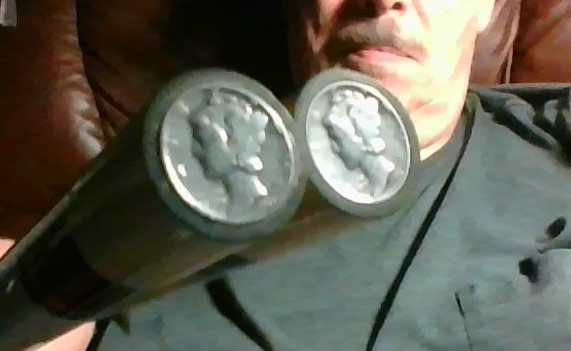
MY MERCURY DIME JOINT PROTECTORS ON MY FAVORITE CUE, A MEUCCI 97-21.
SAME JOINT PROTECTORS SHOWING PIN AND THREADED BUSHING
THESE ARE FOR A 5/16 X 18 JOINT
THESE ARE FOR A 5/16 X 18 JOINT
UPGRADING AND ACCESSORIZING THE HARBOR FREIGHT OR GRIZZLY MINI LATHE. These lathes have their greatest appeal in PRICE, and while they are a good buy still they have room for improvement depending on what you use them for. I have made the following improvements or upgrades to my Harbor Freight 7 X 10 Mini Lathe (Central Machinery 93212). These upgrades are available from Littlemachineshop.com and they are VERY helpful in helping people with upgrades. Any imperfect part is quickly replaced at their expense should this occur. Here is a list of UPGRADES AND ACCESSORIES I have personally made to my lathe all of which were outstanding improvements:
1. CARRIAGE STOP: P/N 2705 "Carriage Stop, Mini Lathe, Adjustable" from Littlemachineshop.com. A carriage stop is a handy tool that allows a stop point for making perfect shoulders and has other uses.
2. CARRIAGE LOCK. P/N 2977 from Littlemachineshop.com. Locks the carriage for precision facing.
3. QUICK CHANGE TOOL POST: P/N 3112, Quick Change Tool Post Set, 0XA, Tormach. OXA WEDGE TYPE FROM LITTLEMACHINESHOP. The QC tool posts eliminate shimming and time consuming tool bit changes.
4. INDEX CARBIDE BITS AND HOLDERS... AN EBAY PURCHASE: 3/8" 5 PC INDEXABLE CARBIDE INSERT LATHE TURNING TOOL BIT INSERT SET.
5. P/N 2018 Tailstock Cam Lock Kit from Littlemachineshop.com. Eliminates the hassle of wrench and nut adjustment of m tailstock.
6. FOUR JAW INDEPENDENT CHUCK. P/N 1175 Lathe Chuck 4 jaw 3" from Littlemachineshop.com.
7. FOLLOWER REST. P/N Follower Rest, Mini Lathe, Ball Bearing. From Littlemachineshop.com. Fits on 2 threaded holes on the carriage.
8. 20TPI KIT. P/N 2383 Feed Screw Parts, 20 TPI, Mini Lathe. For lathes which have the improper inaccurate graduations.
9. APRON GEAR COVER. A must have to prevent lathe debris from jamming up the carriage travel gears.
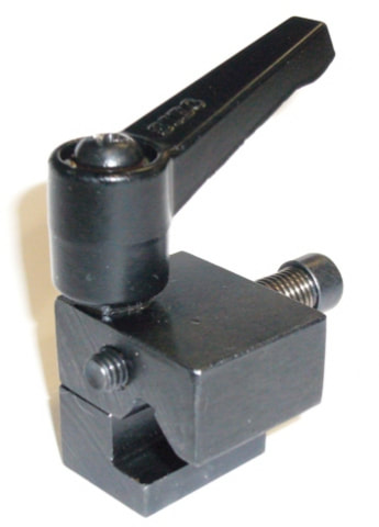
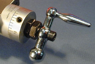
THE CARRIAGE STOP IS A VERY USEFUL TOOL FOR RETURNING TO AN EXACT POINT.
THE HANDLE LIFTS AGAINST A SPRING TO ACT AS A RATCHET MECHANISM.
THE HANDLE LIFTS AGAINST A SPRING TO ACT AS A RATCHET MECHANISM.
This carriage lock P/N 2977 is made to fit a long list of mini-lathes. See this list on the page for this part on the littlemachineshop.com site. Attaches to the threaded holes on the left side of the carriage on many Chinese made mini-lathes. These are the same holes which also accept the follower rest. These holes are plugged with screws at the factory to prevent the holes from becoming plugged with debris. There was only one problem with the Carriage lock on my 7X10 lathe. It works fine as long as the crosslide is not advanced as far as the lathe center. But when I use a boring bar I must advance the crosslide further and the compound rest collides with the screw head on the carriage lock. I solved this problem by removing the phillips head screw, washer and spring from the carriage lock. This allows the lever handle to be removed after the carriage is locked and it can be set aside until needed to unlock the carriage, or the lever can be just left on the post if desired. I have the 93212 Harbor Freight lathe. Most other lathes will not have this clearance problem.
|
|
|
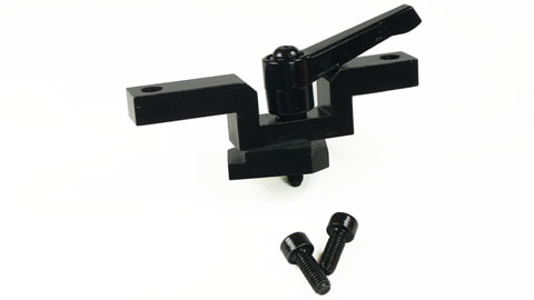
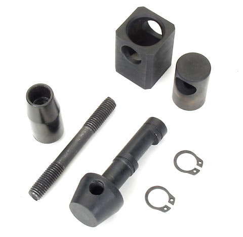
THE TAILSTOCK CAM KIT. THIS UPGRADE REQUIRES DILLING A 1/2" HOLE IN THE SIDE OF THE TAILSTOCK.
The effort is worth it. This kit converts a standard mini lathe tailstock to lock by lever action. This camlock action locks the
tailstock to the ways by moving a lever about 45 degrees. PHOTOS: 1. The kit 2. The tailstock 3. The tailstock with kit installed.
The effort is worth it. This kit converts a standard mini lathe tailstock to lock by lever action. This camlock action locks the
tailstock to the ways by moving a lever about 45 degrees. PHOTOS: 1. The kit 2. The tailstock 3. The tailstock with kit installed.
THE FOLLOWER REST... I purchased this one from Littlemachineshop.com which fits the 7 X 10/12/14 mini lathes. Littlemachineshop describes its application: "The follower rest mounts on the saddle and moves with the cutting tool to provide support where it is needed. On the left side of the carriage (the part that actually slides on the ways) there are two threaded holes with set screws in them. Remove the set screws (that are there to keep the holes clean) and bolt on the follower rest."
THE LITTLEMACHINESHOP P/N 2383 Feed Screw Parts, 20 TPI, Mini Lathe
These parts change Grizzly, Harbor Freight, Homier, and Cummins mini lathes
to 20 thread per inch feed screws on the cross slide and compound rest.
Each rotation of the hand wheel will advance 0.050".
These parts change Grizzly, Harbor Freight, Homier, and Cummins mini lathes
to 20 thread per inch feed screws on the cross slide and compound rest.
Each rotation of the hand wheel will advance 0.050".
ABOUT THE 20 TPI KIT, "2383 Feed Screw Parts, 20 TPI, Mini Lathe" from Littlemachineshop.com.
This is a great kit and Littlemachine shop was very good at helping me with problems. The compound slide graduated nut was causing binding and they replaced it free of charge free shipping which solved the problem. Also the cross slide had a .007" slack with the kit instlled. My lathe originally had a .003" slack which was annoying enough. Littlemachineshop was willing to change parts but I took this opportunity to solve the slack problem COMPLETELY by making a .007" shim. The cross slide now has practically zero slack. My email to them explained the success of this effort:
If you recall, I had mentioned that there was a .007" unacceptable slack in the cross slide control after I installed the 20 TPI kit. You offered to send a new retainer but I wasn't sure if the slack was caused by the retainer or the feed screw or both so I declined the offer. I said I was going to try to shim the cross slide feed. I ordered some .007" steel shim stock from another supplier and I made a shim to fit on the cross slide feed screw which would go over the threaded end and take out the slack between the shoulder on the feed screw and the cross slide body. I had to thin the shim to about .0068" with a whetstone and the end result was perfection. There is zero slack and the wheel turns smoothly as well, no binding, no slack. Of course I still do not know whether it is the feed screw or the retainer that caused the slack I can't say but it is one or the other.
The reason I wanted to shim is because I hoped for a near zero slack which is even better than what the manufacturer engineered into this lathe. With my shim this zero slack was attained with great satisfaction. It is easier to shim out a .007" slack than a .003" which is usually what these lathes have as built so to me the slack was a fortunate invitation to improve the performance of the cross slide. Thin shims of .002" or .003" would tend to tear easily or fold inside cutting shears.
I drilled the hole in the shim tightly clamped and sandwiched between two pieces of wood. This way the hole is clean and the drill doesn't bite. I then tin snipped to attain close to the outside dia. and ground it round on the grinder holding it with pliers and finished the edge with a whetstone by hand. With experimentation I fine tuned the thickness from .007" to @ .0068" to attain a smooth and unbinding crank control of the cross slide. The end product result was a round shim with an O.D. of .587" with a hole .366". The shim has improved my lathe beyond the original engineering and has eliminated a lot of problems with chattering, vibration and over bite of the tool bit especially when using a longer holder-bit tip distance and when using parting (cutoff) bits.
Telling you all this so if someone needs help you can tell them how I improved the lathe. Also it might be a good idea to manufacture and sell shim kits with various thicknesses that can be used singly or stacked to take the factory slack out of the Harbor Freight / General Machinery mini-lathes. Wayne
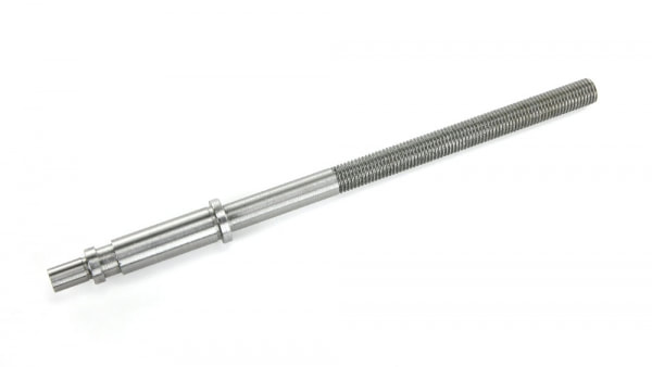
THE 20 TPI CROSS SLIDE FEED SREW. SLACK IN THE CROSS SLIDE WAS REMOVED BY MAKING A WASHER SHAPED SHIM
WHICH WAS SLIPPED OVER THE THREADED END TO REST AGAINST THE SHOULDER, REMOVING SLACK IN THE FEED.
WHICH WAS SLIPPED OVER THE THREADED END TO REST AGAINST THE SHOULDER, REMOVING SLACK IN THE FEED.
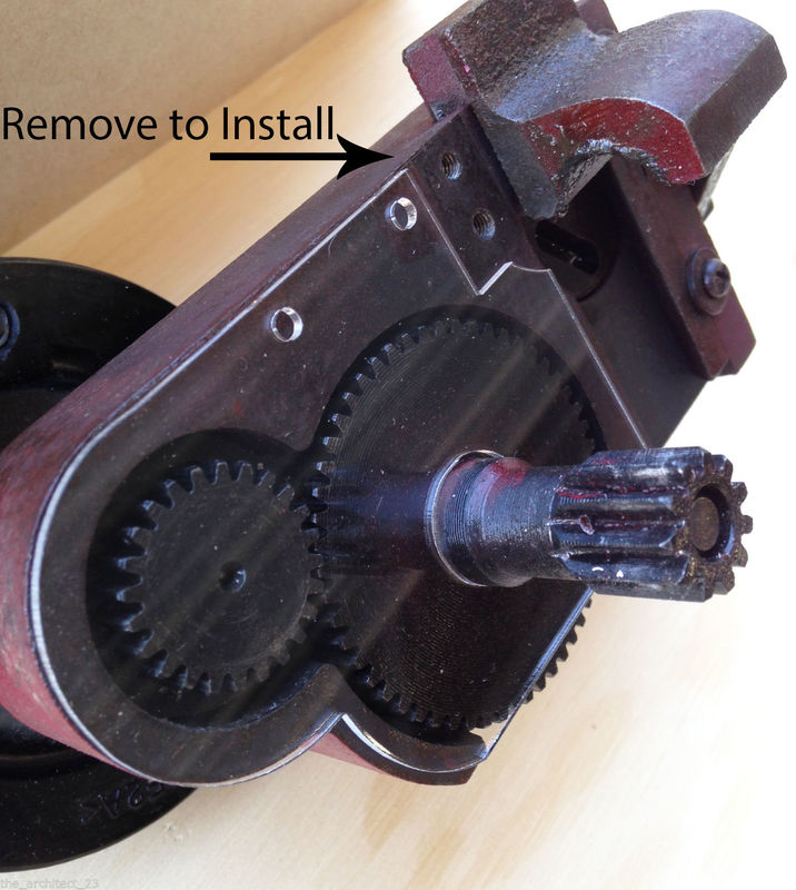
|
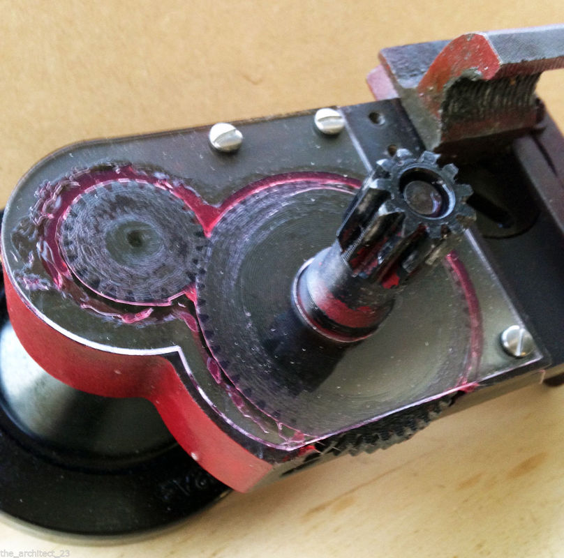
|
THE MINI-LATHE APRON GEAR COVER... A MUST HAVE ACCESSORY. This cover keeps debris from jamming the gears on the carriage. If needed, videos are available on the internet which show how the apron is removed from the lathe. The apron must be removed from the ways and three holes drilled and tapped to mount the cover in place. I used 6-32 screws. Without this cover my gears got impacted with wood and plastic particles and the travel crank was very stiff to turn. Spraying in there with WD40 helped but only attracted more debris. Occasionally a chip would lodge in there stopping the carriage completely and I had to make a wire probe from a paper clip to dislodge it. The installation of the cover took some time but was well worth it. There was some rubbing of the cover against the lead screw shroud but with a little oil and a few passes the carriage moved freely. The cover pictured above was purchased off ebay from the seller the_architect-23 and is the one I purchased for my lathe. They are also available from littlemachineshop.com. Cleaning the gears up, re-greasing them and installing the cover made life much better. I am surprised these weren't installed on these lathes during manufacture.
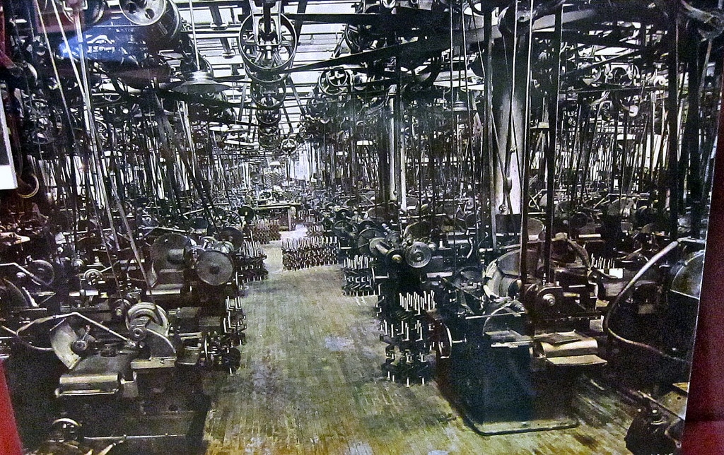
I WAS JUST THINKING ABOUT A BIGGER ROOM FOR MY LATHE
MY SHOP. My setup was primarily arranged for repairing pool cues, modifying shafts etc. Since I am walking limited I enjoy sitting down at the lathe. I am able to place my legs under the 7 x 10 Harbor Freight (Central Machinery) lathe in this setup with the lathe mounted on a 2x12 which is c-clamped to the top of a homemade cabinet/stand. I have made 2x4 outriggers topped with 6" window sill to hold the roller rests. The room is small with a usable space of @ 7 x 8 feet leaving @ 2 1/2 feet between the lathe and the bench for me to place my swivel chair so it is just a matter of rotating in the chair to leave the lathe and go to the grinder bench. To place a house cue in the lathe I have placed a piece of rug under the stand so it will slide and I pivot the end of the lathe over a few inches so the axis of the roller rest to spindle points out the door into the kitchen. My grinder bench is an antique cast iron stove base with two layers of 3/4 plywood set into the top where the stove would go. My chair is an antique heavy duty castor swivel secretary chair. The drill press has a cross slide is on the drill press platen which is rotated to the side so it doesn't interfere with my chair when I am turned toward the lathe. Antique tools and implements cover the walls. The old Kennedy chest and riser box hold my collection of vintage and antique machinist tools. My website tells more about my work and has a slideshow of my antique tool wall. Also the site discusses the upgrades to this lathe. BTW the Stanley 1 Gallon Shop Vac was small and powerful and a great addition to this small shop. You might notice two aluminum pie plates to deflect sparks from the grinder.
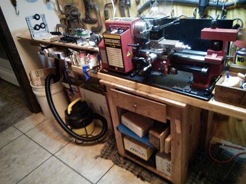
|
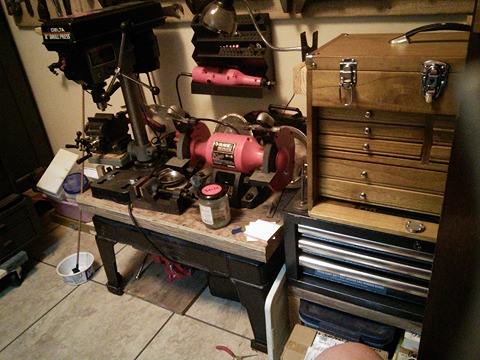
|
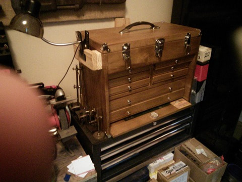
|
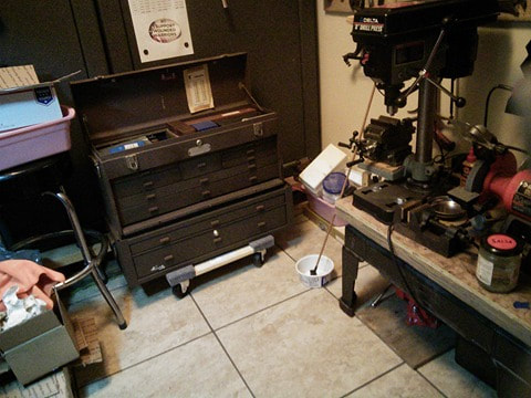
|

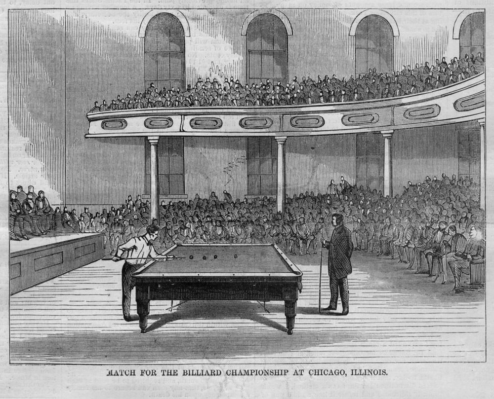
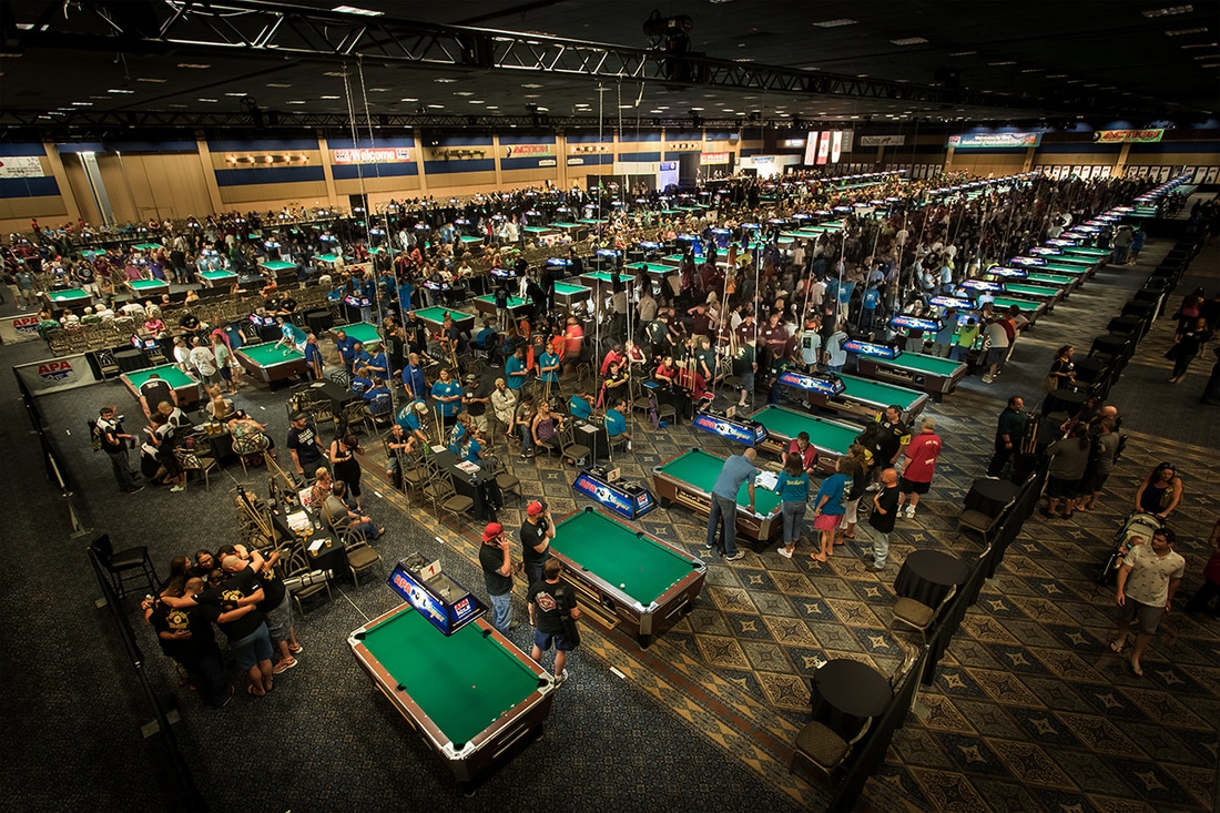
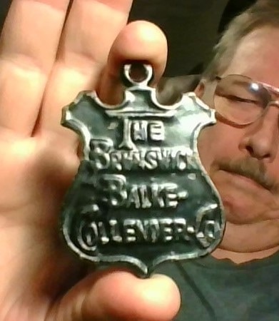
ANTIQUE CAST IRON CHALK COUNTERWEIGHT BY THE BRUNSWICK BALKE COLLENDER COMPANY. IN THE OLD POOL HALLS CHALK HUNG FROM THE CEILING BY A COUNTERWEIGHTED STRING AND PULLEY SYSTEM RIGGED OVER THE POOL TABLES. THE PLAYER JUST REACHED UP FOR THE CHALK TO CHALK HIS CUE.
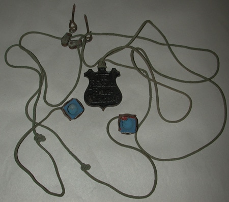
BELOW IS A SLIDE SHOW OF THE ANTIQUE TOOL COLLECTION ON MY LATHE ROOM WALL. ENJOY.

HI, MY NAME IS BABY.
I AM A RESCUE DOG. PLEASE SUPPORT ASPCA OR
RESCUE KENNELS AND RESCUE ORGANIZATIONS.
I AM A RESCUE DOG. PLEASE SUPPORT ASPCA OR
RESCUE KENNELS AND RESCUE ORGANIZATIONS.

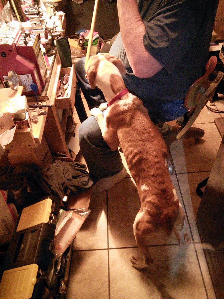
WORKING ON CUES AT THE LATHE, LUCKY COMES IN FOR A VISIT. WE HAD JUST GOT HER WHEN THIS PHOTO WAS TAKEN. SHE WAS ALMOST STARVED AND HAD HEARTWORMS, HOOKWORMS, PYOMETRA AND OTHER ISSUES WHEN FOUND. A FEW TRIPS TO THE VET AND A LOT OF CARE AND IN TIME SHE BECAME THE HEALTHY GIRL BELOW. DOGS ARE THE BEST PEOPLE.
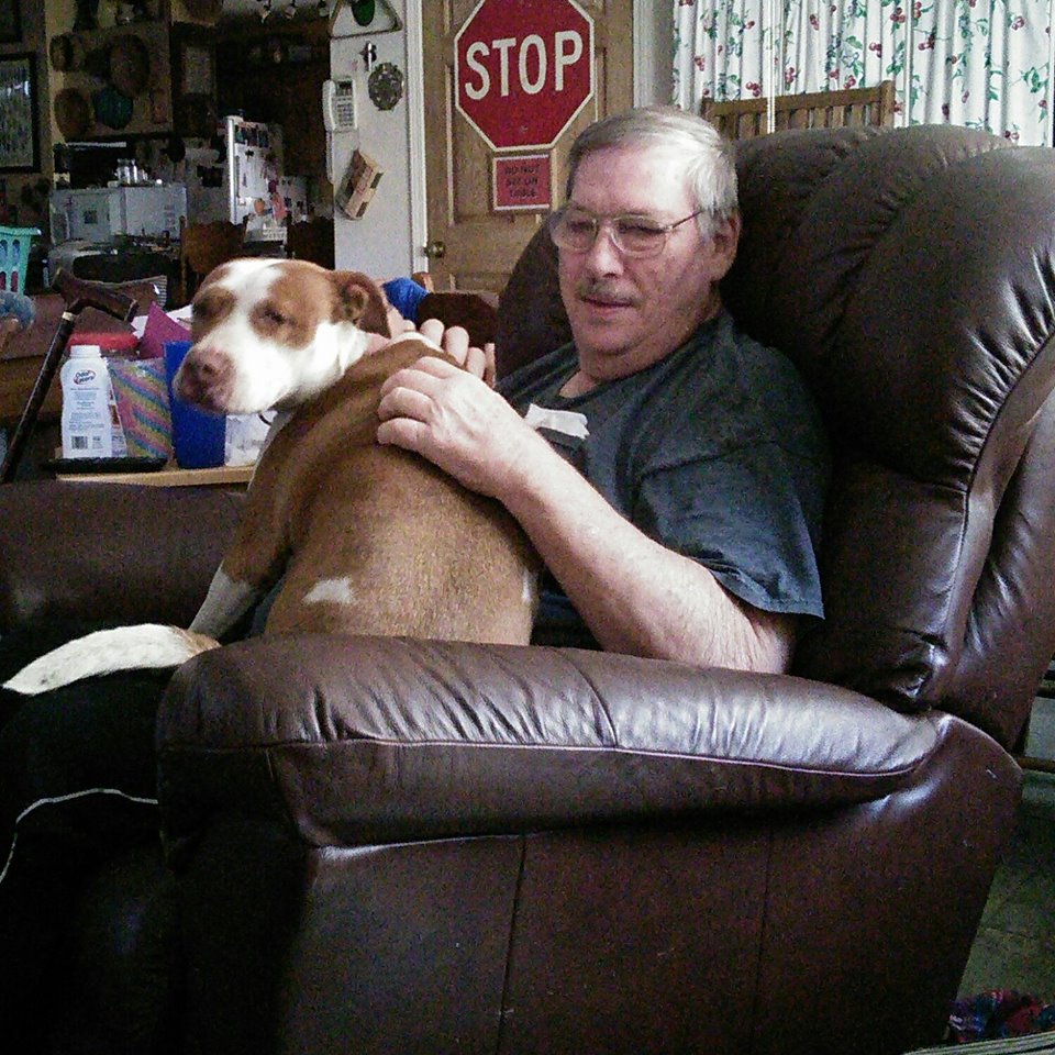

|
MY WORK
PORTRAITS
LANDSCAPES ANIMALS SPORTS |
|


EQUIPMENT
HARBOR FREIGHT CENTRAL MACHINERY 7 X 10 MINI-LATHE 93212
BLACK & DECKER BT3500 6" BENCH GRINDER
DELTA 8" BENCH DRILL PRESS WITH ADDED XY CROSSLIDE VISE
DRILL DOCTOR 350X DRILL BIT SHARPENER
8 DRAWER WOOD TOOL CHEST HARBOR FREIGHT
8 DRAWER KENNEDY 526 MACHINIST TOOL CHEST WITH MC-28 RISER
WEN 74603 3 DRAWER INTERMEDIATE CHEST 26"
BLACK & DECKER BT3500 6" BENCH GRINDER
DELTA 8" BENCH DRILL PRESS WITH ADDED XY CROSSLIDE VISE
DRILL DOCTOR 350X DRILL BIT SHARPENER
8 DRAWER WOOD TOOL CHEST HARBOR FREIGHT
8 DRAWER KENNEDY 526 MACHINIST TOOL CHEST WITH MC-28 RISER
WEN 74603 3 DRAWER INTERMEDIATE CHEST 26"
